-51-
Item Specification
2.
Life: on/off total count 60,000<
3.
Continuous open/shut frequency: 3Hz>
Emission range
420
~
700nm
BA (barrier) filter
1.
Standard: None
2.
Option: BA line-up is shown in the Table 7-2-2
(
CAUTION
) You must install optimal BA filter to match
the laser and DM.
BA filter position and
exchange
1.
Basic model
One position in the filter slot at each of 1
st
and 2
nd
camera port. Filter size:
φ
25mm
2. High-end Model
* To use Filter Wheels installed in the filter slot at each
of 1
st
and 2
nd
camera port
* CSU-X1FW-06P-01: Filter Wheel for 1
st
camera port
* CSU-X1FW-06P-02: Filter Wheel for 2
nd
camera port
* CSU-X1CU-F1 control unit is required to use
CSU-X1FW-06P-01.
Bright Field
(Non-confocal)/Confocal
switching
1 Light path exchange (High-end mode)
:
* Motor driven: Requires CSU-X1CU-B1(Bright Field
control unit)
2 Light path exchange (Basic mode)
* Manually exchange two ports with each lever
Microscope connection
1.
Standard: C mount of each microscope
2.
Option for Bright Field:
Microscope specific connectors are necessary to install
Bright Field unit. Specific connectors for Olympus,
Nikon, Zeiss, Leica , upright/inverted microscopes are
available as option.
Switching between 1
st
and
2
nd
camera port
1 .Light path exchange (High-end model)
:
Motor driven: Requires CSU-X1CU-B1(Bright Field
control unit)
2 Light path exchange (Basic model)
Manual exchange with a port exchange lever
Camera port
1.Standard
:
* 1
st
camera port: C mount
(
X 1
)
* 2
nd
camera port position: covered
2.Option
:
* 2
nd
camera port with C mount (X 1)
* C mount adapter for EMCCD (X 1.2 for 8×8mmCCD
chip
)
available for both 1
st
/2
nd
camera port
* Eye piece for direct view of confocal image at 2
nd
port.
(
WARNING
) To install the direct view eye piece,
appropriate barrier filter to cut the excitation laser has
to be installed for laser safety.
Summary of Contents for CSU-X1
Page 1: ...User s Manual Confocal Scanner Unit CSU X1 IM 85A7C25 02E IM 85A7C25 02E 1 Edition...
Page 2: ......
Page 5: ...4 7 4 Control Signal 66 8 Command list 73 9 Warranty 75...
Page 6: ......
Page 15: ...13 Figure 1 3 Positions to attach warning labels to CSU X1 M2 E...
Page 16: ...14 Figure 1 4 Positions to attach warning labels to CSU X1 A2 E...
Page 17: ...15 Figure 1 5 Positions to attach warning labels to CSU X1 A3 E...
Page 18: ...16 Figure 1 6 Positions to attach warning labels 6 CSU X1 M1 CSU X1 A2 CSU X1 A3 CSU X1 FW...
Page 19: ...17 Figure 1 7 Examples of warning labels attached to the microscope...
Page 39: ...37 3 3 4 Connection Diagram CSU X1 A1 CSU X1 A2 Microscope Camera Microscope Camera...
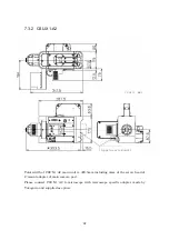
Page 67: ...65 7 3 6 CSU X1CU 7 3 7 CSU X1FW Unit mm Unit mm...
Page 78: ......
Page 79: ...User s Manual CSU Control Unit CSUX1CU IM 85A7C26 02E IM 85A7C26 02E 1st Edition...
Page 80: ......
Page 82: ......
Page 98: ...18 4 Name and Function 1 2 3 4 5 6 7 8 9 10 11 12 13...
Page 117: ...User s Manual Filter Wheel CSUX1FW IM 85A7C27 01E IM 85A7C27 01E 1st Edition...
Page 118: ......
Page 120: ......
Page 132: ...14 4 Name and function 1 2 3 4 5 9 17 18 19...
Page 140: ...22 6 3 Dimension of CSUX1FW...


