background image

IM 12J05S01-01E

2-1

2.  Installation and Wiring

2.

Installation and Wiring

2.1

Installation

2.1.1

Installation Location

Since power supply unit is waterproof, you can install it outdoors.  Be sure to install it
as close to the converter as possible.

Note:
Avoid installing the unit in ambient air containing excessive moisture or corrosive gas.

If the case cover is not closed tightly in excessive moisture or corrosive gas, the unit
may suffer problems such as insulation failure, disconnection, or poor contact.

2.1.2

How to Mount

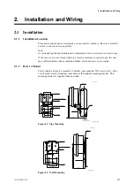
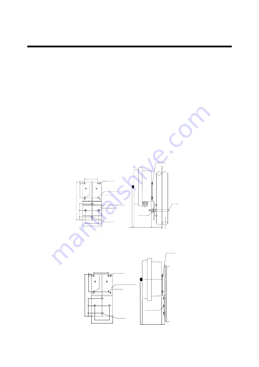
Power supply unit can be mounted on bracket, pipe (nominal 50A size) or wall.  How-
ever for pipe or wall mounting, order and use the optional mounting bracket.  This
mounting bracket is supplied when specified.

Nominal 50A 

U-bolt

4-M5 screw

10

90

56

Pipi mounting bracket 2

Pipe mounting bracket 1

200

±

0.5

100

70

35

35

15

75

8

70

5- 

6.5 holes

6.5

13 hole

2- 

9

±

0.5 holes

4- 

10 holes

Weight: 0.7 kg

Unit : mm

(O.D. 

60.5 pipe)

M8 nut 

2

2- 

5.5 holes

Figure 2.1  Pipe Mounting

Wall mounting bracket

70

8

75

15

35

35

70

100

200

±

0.5

4-M5 screw

4-M8 screw

10

90

15

Weight: 0.7 kg

Unit : mm

5- 

6.5 holes

2- 

5.5 holes

4- 

10 holes

6.5 

13 hole

Figure 2.2  Wall Mounting

Summary of Contents for DOX10

Page 1: ...User s Manual IM 12J05S01 01E Model DOX10 Power Supply Unit IM 12J05S01 01E 1st Edition ...

Page 2: ...red as an option 2 Information Described in This Manual This manual describes information on the specifications installation and wiring of the DOX10 For information on wiring to DO402G refer to IM 12J05D02 01E The table below shows the instruction manuals of the relevant equipment used in the dissolved oxygen measuring system Table Manuals of Relevant Equipment Used in Dissolved Oxygen Measuring S...

Page 3: ...paired 2 Safety and Modification Precautions Follow the safety precautions in this manual when using the product to ensure protection and safety of the human body the product and the system containing the product 3 The following safety symbols are used on the product as well as in this manual DANGER This symbol indicates that an operator must follow the instructions laid out in this manual in orde...

Page 4: ...ee regardless of warranty period Failure of components which are out of scope of warranty stated in instruction manual Failure caused by usage of software hardware or auxiliary equipment which Yokogawa did not supply Failure due to improper or insufficient maintenance by user Failure due to misoperation misuse or modification which Yokogawa does not authorize Failure due to power supply voltage fr...

Page 5: ...IM 12J05S01 01E iv Introduction ...

Page 6: ...and Wiring 2 1 2 1 Installation 2 1 2 1 1 Installation Location 2 1 2 1 2 How to Mount It 2 1 2 2 Wiring 2 2 2 2 1 Connecting Sensor Cable 2 3 3 Inspection and Maintenance 3 1 3 1 Power Supply Unit Inspection 3 1 3 1 1 Checking for Moisture and Performing the Required Maintenance 3 1 3 1 2 Checking for Corrosion and Performing the Required Maintenance 3 1 Customer Maintenance Parts List CMPL 12J05...

Page 7: ...IM 12J05S01 01E ...

Page 8: ...uit adaptor optional available Ambient temperature 10 to 55ºC Humidity range 10 to 90 RH non condensing Power supply 100 115 230V AC 50 60Hz Acceptable range Rated Voltage 15 Output voltage 24V DC 1V Terminal M4 screw Weight Body Approx 1 6 kg Mounting bracket Approx 0 7 kg Attached cable Approx 0 3 kg 1 2 Model and Suffix Codes DOX10 power supply unit Power supply Cable length 00 15 N Option Moun...

Page 9: ... 2 36 10 275 203 Sensor cable inlet Converter cable inlet Power cable inlet 4 M5 screws depth 10mm a Watertight plastic cable gland St d for mounting Adaptor 49 Approx 55 Adaptor for Conduit Weight Approx 1 6kg G1 2 female CB1 1 2 NPT female CD1 M20 1 5 CF1 Attached cable with DOX10 Not supplied if suffix code 00 N is selected Cable length 1 5 m G N L G N L Black L White N Red G White N Black L Re...

Page 10: ...ing bracket 1 200 0 5 100 70 35 35 15 75 8 70 5 6 5 holes 6 5 13 hole 2 9 0 5 holes 4 10 holes Weight 0 7 kg Unit mm O D 60 5 pipe M8 nut 2 2 5 5 holes Wall mounting bracket for power supply unit optional option code W Wall mounting bracket 70 8 75 15 35 35 70 100 200 0 5 4 M5 screw 4 M6 screw 10 90 15 Weight 0 7 kg Unit mm 5 6 5 holes 2 5 5 holes 4 10 holes 6 5 13 hole ...

Page 11: ...IM 12J05S01 01E 1 4 ...

Page 12: ...connection or poor contact 2 1 2 How to Mount Power supply unit can be mounted on bracket pipe nominal 50A size or wall How ever for pipe or wall mounting order and use the optional mounting bracket This mounting bracket is supplied when specified Nominal 50A U bolt 4 M5 screw 10 90 56 Pipi mounting bracket 2 Pipe mounting bracket 1 200 0 5 100 70 35 35 15 75 8 70 5 6 5 holes 6 5 13 hole 2 9 0 5 h...

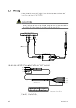
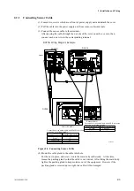
Page 13: ... with the sensor cable K9679HA DOX10 attached cable 11 Clear Red BROWN BLUE White Green Green Yellow 18 17 14 12 G N L L N G L N G BLUE BROWN DO402G Converter DO70G AC IN TO CONVERTER DOX10 Power Supply Unit Attached cable with DOX10 Not supplied if suffix code 00 N is selected Cable length 1 5 m G N L G N L Black L White N Red G White N Black L Red G 80 50 Model and Suffix Code Approx 1 500 DOX10...

Page 14: ...g color DO70G Red Clear Green Yellow Green White DO402G Terminal No 18 17 14 12 11 BROWN BLUE Wiring color DO70G BROWN BLUE DOX10 Terminal No K9679AX Connections of the sensor cable and DO402G terminals are shown in the following table Connections of the sensor cable and DOX10 terminals are shown in the following table Figure 2 4 Connecting Sensor Cable 4 Mount the cable gland in the cable inlet h...

Page 15: ...IM 12J05S01 01E 2 4 ...

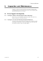
Page 16: ...it Inspection 3 1 1 Checking for Moisture and Performing the Required Maintenance Remove the cover of the terminal box and check for moisture If the inside is very damp use a hair drier to dry the inside of the box 3 1 2 Checking for Corrosion and Performing the Required Maintenance Check that corrosive gas has not entered the terminal box and corroded the terminals and conductors If the corrosion...

Page 17: ...IM 12J05S01 01E 3 2 ...

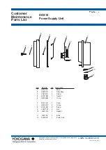
Page 18: ...ower Supply Unit CMPL 12J05S01 01E 8 7 6 5 4 3 2 1 9 10 11 12 Item Part No Qty Description 1 K9141LA 1 Case 2 K9679FG 1 Plate Assy 3 Y9408LU 4 Screw 4 K9141MB 1 Gasket 5 G9303NB 1 O ring 6 K9141LD 1 Case 7 G9303NF 2 O ring 8 K9141MH 2 Screw 9 L9811FM 3 Nut 10 L9811FN 3 Gasket 11 L9811FE 3 Body 12 A1630UP 1 Power Unit 1st Edition Jan 2012 ...

Page 19: ......

Page 20: ...Revision Record Manual Title Model DOX10 Power Supply Unit Manual Number IM 12J05S01 01E Edition Date Remark s 1st Feb 2012 Newly publishd ...

Page 21: ......
Reviews: