<4. Installing Impulse Piping>
39
IM 01C25A01-01E
4.
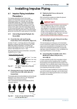
Installing Impulse Piping
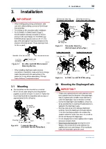
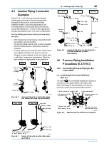
4.1 Impulse Piping Installation
Precautions
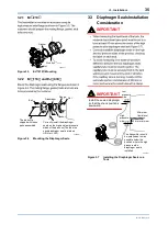
4.1.1 Connecting Impulse Piping to the
Transmitter
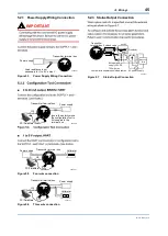
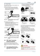
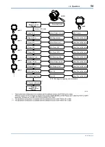
(1) Check the High and Low Pressure
Connections on the Transmitter (Figure 4.1)
F0401.ai
Process
connection
“H” and “L” are shown
Process connection
Process connector
Bolt
Differential Pressure Transmitter
Figure 4.1
“H” and “L” Symbols on a Capsule
Assembly
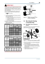
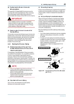
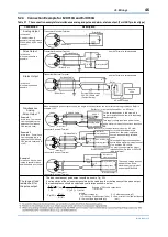
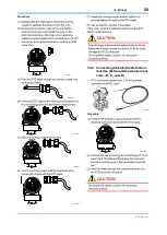
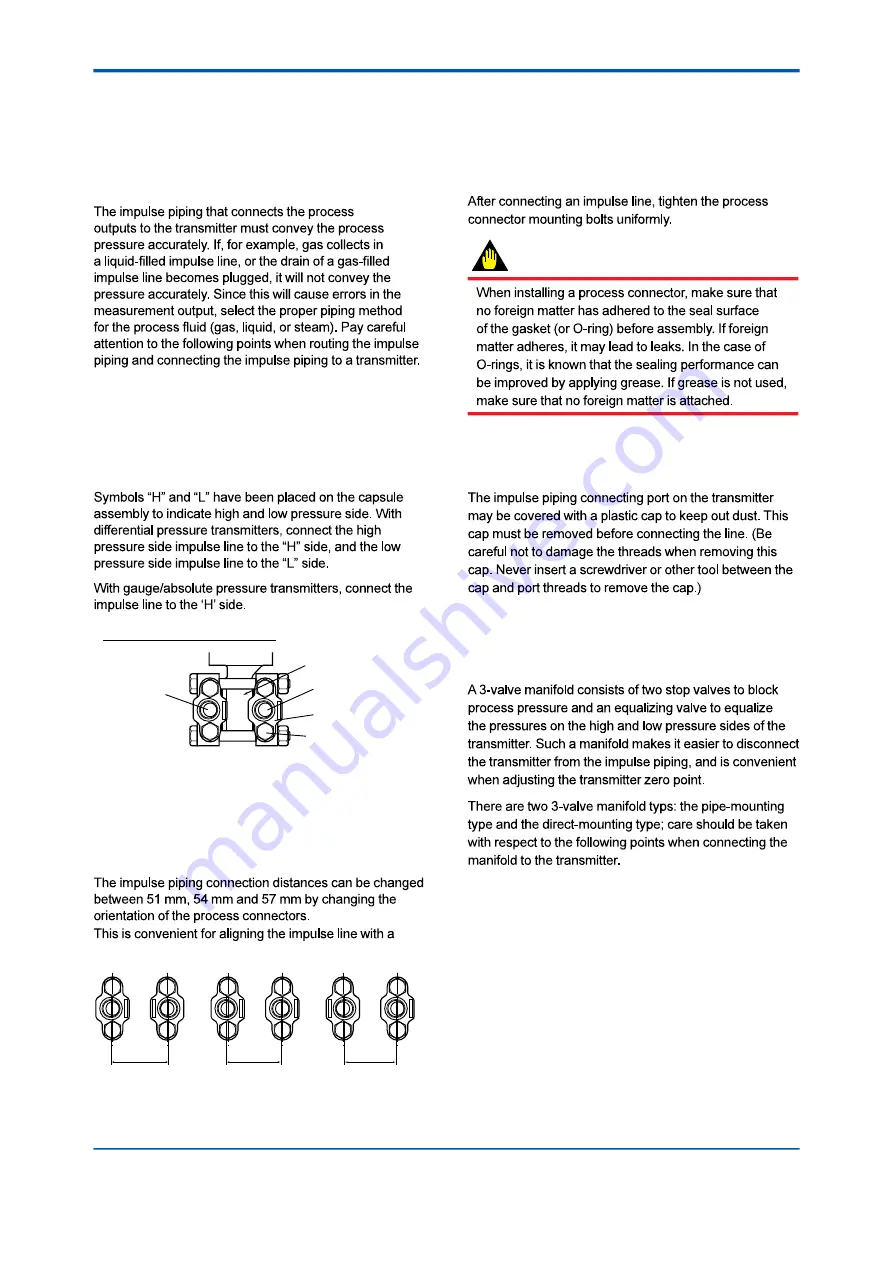
(2) Changing the Process Connector Piping
Connections (for differential pressure
transmitters)
process connectors.
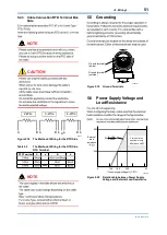
57 mm
54 mm
51 mm
F0402.ai
Figure 4.2
Process Connector Impulse Piping
Connection Distances
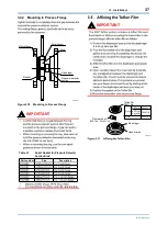
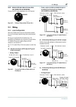
(3) Tightening the Process Connector
Mounting Bolts
IMPORTANT
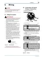
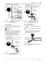
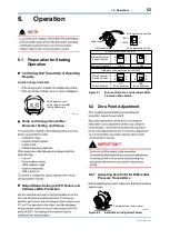
(4) Removing the Impulse Piping Connecting
Port Dustproof Cap
(5) Connecting the Transmitter and 3-Valve
Manifold (for differential pressure
transmitters)