6-115
TI71M01D06-01EN 3rd Edition: 2012.12.01
6.8 Area
Signal
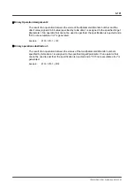
Two area signal channels are provided. When a position range is specified by certain
parameter values in advance, these signals indicate whether or not the motor position is
within the indicated range. The status is output to the OUT_AREA_0 and OUT_AREA_1
signals of the controller interface and parameter #321 [Status register 2 (bits 26 and 27)] of
the utility software.
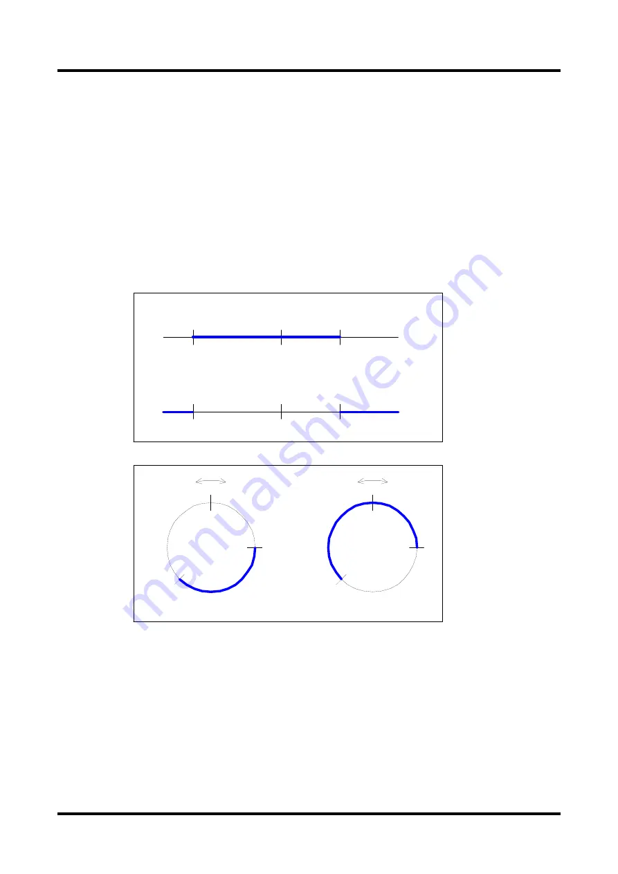
The area signal range is set by specifying the coordinate value at which the signal is turned
ON in parameters #46 [Area signal 0 ON] and #48 [Area signal 1 ON] in command units, and
specifying the coordinate value at which the signal is turned OFF in parameters #47 [Area
signal 0 OFF] and #49 [Area signal 1 OFF] in command units. The signal output as a function
of the motor position, #376 [Actual position value in command units], varies with the greater of
the coordinate values whereby the signal is turned ON or OFF. The figures below show how
the signal is output in case the linear coordinate system or the rotation coordinate system is
selected, respectively.
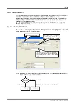
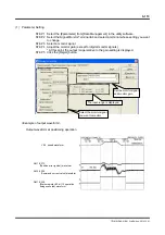
Parameter Setting
STEP 1 Select [Terminal] from [Control].
STEP 2 Set the parameters for the area signal range in the Terminal window.
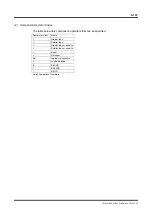
Hard I/O Assignment Setting
STEP 1 Select [I/O] from [Data Management] in the utility software.
STEP 2 Assign area signal 0 or area signal 1 in the hard I/O contact output assignment
window.
0
+
−
ON
OFF
0
+
−
OFF
ON
0
−
+
ON
OFF
0
−
+
OFF
ON
[Rotation coordinate system]
The area signal is ON.
ON position < OFF position
The area signal is ON.
OFF position < ON position
[Linear coordinate system]
ON position < OFF position
The area signal is ON.
OFF position < ON position
The area signal is ON.
The area signal is ON.
#47 (#49) setup value
#46 (#48) setup value
#47 (#49) setup value
#46 (#48) setup value

