4-6
TI 71M01D06-01EN 3rd Edition: 2012.12.01
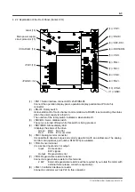
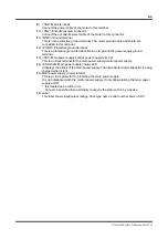
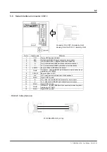
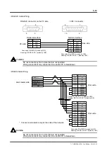
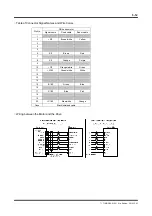
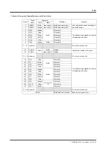
(8) <CN4> CC-Link interface connector
Connect a controller such as PLC corresponding to CC-Link to this connector.
(9) <TB2>
Motor
terminal
Connect the power cable of the motor to this terminal.
(10) <CN2> Encoder/resolver connector
Connect the encoder/resolver cable of the motor to this connector.
(11) <GND> Ground terminal
This is not a protective ground terminal. The motor ground cable and shield are
connected to this terminal.
(12) <PGND> Protective ground terminal.
This is a protective ground terminal. Be sure to ground the power supply ground
terminal.
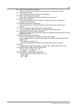
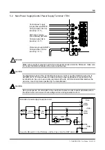
(13) <TB1> Main power supply/control power supply terminal
This is an input terminal for the main power supply/control power supply.
(14) <CHARGE> Main power supply charge LED
It displays the status of the main power supply. The internal electrolyte capacitor is being
charged when it is lit.
(15) Main power supply circuit protector
This is a circuit protector for protecting the main power supply.
It is not interlocked with the control power supply. It only allows turning the main power
supply on/off.
* It is treated as a switch in UL.
Connect a specified fuse externally to acquire the status of UL by a device.
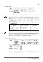
(16) Label
This label shows input/output ratings, drive type name, serial number and so forth.
(17) <STATION NO.> Station number setting switch
It sets the station number of CC-Link.
x1: Lower x10: Upper
(18) <RUN/ERR>Transmission monitor display
It monitors the communication status of CC-Link.
Green: RUN
Red: ERR


