background image


A2-7


IM 34M06H62-02E

3rd Edition : Jul.16, 2015-00


A2.5 Output 

Specifications 

Table A2.5 lists the output specifications of the F3CU04-0S and F3CU04-1S temperature 

control and PID modules. 

Table A2.5   Output Specifications 

Item 

Specification 

F3CU04-0S 

F3CU04-1S 

Number of outputs 

External power supply * 

24 V DC 

10%, 10 mA 

24 V DC 

10%, 250 mA 

Time-proportional PID 
output (open collector 
output)


Rated load voltage 

24 V DC 

Maximum load current 

0.1 A per point 

0.1 A per point and 0.4 A for 8 

points 

ON residual voltage 

0.5 V DC max. 

OFF leakage current 

0.1 mA max. 

Response time 

OFF

ON: 1 ms max., ON

OFF: 1 ms max. 

Cycle time 

0.5 to 240 s 

Time-proportional 
resolution 

10 ms or 0.05% of F.S., whichever is greater 

Continuous PID output 
(analog output) 

Output range 

N.A. 

4-20 mA (3.2-20.8 mA) 

Allowable load 

resistance 

600

 max. 

Output accuracy 

1.0% of F.S. 

Output resolution 

0.05% of F.S. 

External power supply is not required if no output terminal is used (that is, if only input terminals are used). 


A2.6 Backup 

Function 

The F3CU04-0S or F3CU04-1S temperature control and PID module provides a backup 

function for storing input type, input range, set points and other parameter values, and 

hence retaining their values even after power off and on. Parameters designated for 

backup are stored whenever their corresponding registers are updated, provided the 

backup function is not disabled. However, you need to execute a specific procedure 

every time to back up set point values. Otherwise, stored set points will not be updated. 

Even so, beware that set points will not be updated if the backup function is disabled.   
Take note that there is a maximum limit to the number of write operations allowed for the 

backup function. 

Table A2.6   Backup Function 


Description 

Stored parameters 

Controller parameters, I/O parameters, and operation parameters. For details, refer 

to the list of registers. 

Number of write 

operations 

Up to 100,000 write operations allowed 

Disable backup function

This parameter disables the backup function. It may be used, if required, to avoid 

reaching the maximum limit for write operations. 


For details on the I/O data registers that are stored by the backup function and their data 

position numbers, see Section B2, "Types of Relays and Registers." 


In situations where the CPU module frequently overwrites the I/O data registers 

earmarked to be stored by the backup function, the maximum limit for write operations 

(100,000 times) may be reached. To prevent this, turn on the Disable Backup Function 

parameter. Once the write limit is reached, data backup is no longer allowed and the 

system enters hardware failure mode. Furthermore, parameter data may be reset at 

system startup to the default values given in Section B2, "Types of Relays and 

Registers." 


Summary of Contents for F3CU04-0S

Page 1: ...rol and PID Module IM 34M06H62 02E 3rd Edition Yokogawa Electric Corporation Applicable Modules Model Code Model Name F3CU04 0S Temperature control and PID module F3CU04 1S Temperature control and PID...

Page 2: ...Blank Page...

Page 3: ...ogawa Electric Corporation Applicable Product Range free Multi controller FA M3 Model F3CU04 0S F3CU04 1S Name Temperature Control and PID Module The document number for this manual is given below Ref...

Page 4: ...contact the nearest Yokogawa Electric representative or sales office Safety Symbols Danger This symbol on the product indicates that the operator must follow the instructions laid out in this user s...

Page 5: ...l proof design and fail safe design of processes and lines using the product and the system controlled by it the user should implement it using devices and equipment additional to this product If comp...

Page 6: ...the software for use with each additional computer Copying the software for any purposes other than backup is strictly prohibited Store the original media that contain the software in a safe place Rev...

Page 7: ...USE COPPER CONDUCTORS ONLY Use conductors with temperature rating above 75 C Securely tighten screws Securely tighten module mounting screws and terminal screws to avoid problems such as faulty operat...

Page 8: ...ces with high temperature or humidity Since the CPU module has a built in battery avoid storage in places with high temperature or humidity Since the service life of the battery is drastically reduced...

Page 9: ...al before connecting wires Refer to the Hardware Manual IM 34M06C11 01E or the applicable user s manual for the external wiring drawing Refer to A3 6 5 Connecting Output Devices in the Hardware Manual...

Page 10: ...dance with domestic law concerning disposal See the User s Manual of F3RP6 for the removal procedure Take a right action on waste batteries because the collection system in the EU on waste batteries a...

Page 11: ...nual IM34M06Q31 02E Notation References to chapters and sections are denoted by the chapter or section number followed by the chapter or section title enclosed within double quotation marks Relay name...

Page 12: ...ire document is strictly prohibited by the Copyright Law Except as stated above no part of the online manuals may be reproduced transferred sold or distributed to a third party in any manner either in...

Page 13: ...Components and Functions A2 10 A2 9 External Dimensions A2 11 A3 Startup Procedure A3 1 A4 Hardware Preparation A4 1 A4 1 Selecting Input Types and Power Frequency A4 2 A4 2 Attaching Detaching Modul...

Page 14: ...ling Period B3 2 B3 1 3 Controller Mode B3 3 B3 1 4 Setting Output Terminals B3 5 B3 1 5 Sample Program for Setting Controller Parameters B3 6 B3 2 Setting I O Parameters B3 8 B3 2 1 Input Type Select...

Page 15: ...10 Input Filtering C3 15 C3 11 Two input Changeover for use in two input changeover mode only C3 16 C3 12 External Input C3 18 C4 SP Related Functions C4 1 C4 1 Set Point SP C4 2 C4 2 Remote Set Poin...

Page 16: ...n C8 6 C8 3 Alarm Delay Timer C8 7 C8 4 Selecting Alarm Preset Values C8 7 C9 Disable Backup Function C9 1 C10 Self diagnosis Function C10 1 C10 1 How to Check for Errors C10 2 C10 2 List of Error Sta...

Page 17: ...al Specifications A2 4 Input Specifications A2 5 Output Specifications A2 6 Backup Function A2 7 Function Specifications A2 8 Components and Functions A2 9 External Dimensions A3 Startup Procedure A4...

Page 18: ...Blank Page...

Page 19: ...r controlling four loops The controller functions can be configured to act inter dependently or independently to support a wide variety of applications Three controller modes are available single loop...

Page 20: ...g operation is to simply set the input type output type and set point The dynamic auto tuning function automatically determines and tunes the PID parameters during operation You may disable the functi...

Page 21: ...fix Codes Model Suffix Code Style Code Option Code Description F3CU04 0S 4 loops Universal input Time proportional PID output open collector Single slot size 1S 4 loops Universal input Universal outpu...

Page 22: ...etails see the External Dimensions drawing A2 4 Input Specifications Table A2 3 lists the input specifications of the F3CU04 0S and F3CU04 1S temperature control and PID modules Table A2 3 Input Speci...

Page 23: ...trument range If the input type is thermocouple and reference junction compensation is used you should also take into consideration the accuracy of the reference junction compensation 5 For K type the...

Page 24: ...hen you turn on the power after changing the hardware switch settings data stored in the EEPROM is initialized to follow the switch settings 4 This accuracy applies if the ambient temperature is 25 5...

Page 25: ...ambient temperature is 77 F 9 F and the input value is within the instrument range If the input type is thermocouple and reference junction compensation is used you should also take into consideratio...

Page 26: ...urn on the power after changing the hardware switch settings data stored in the EEPROM is initialized to follow the switch settings 4 This accuracy applies if the ambient temperature is 77 F 9 F and t...

Page 27: ...d whenever their corresponding registers are updated provided the backup function is not disabled However you need to execute a specific procedure every time to back up set point values Otherwise stor...

Page 28: ...nges PV range setting Sets PV range for two input changeover mode Burnout selection Selectable from Up scale Down scale or OFF no burnout detection for thermocouple or RTD input open circuit detection...

Page 29: ...ation Forward reverse operation Defines the direction of output change increase or decrease corresponding to a positive deviation PID control mode The combination of the CMD parameter 0 standard PID c...

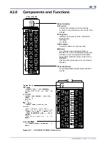
Page 30: ...60 Hz green Indicates the frequency of the commercial power supply Off 50Hz On 60 Hz ALM orange Lit when an alarm occurs in any loop ERR red Lit or flashes when a hardware failure is detected or an er...

Page 31: ...2 Right Side View Showing Input Type and Power Supply Frequency Selector Switches You may switch the temperature unit between C and F using SW1 1 For details see Section C11 Selecting Temperature Uni...

Page 32: ...Blank Page...

Page 33: ...quired system components when performing setup are the power supply module the base module the CPU module software and a personal computer for running the software For details on the required environm...

Page 34: ...Blank Page...

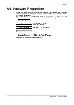
Page 35: ...must set the operation switches and perform wiring connections In this chapter we describe the details of hardware preparation Figure A4 1 shows the workflow for hardware preparation For details on e...

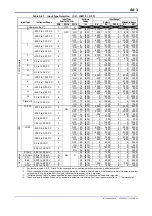
Page 36: ...a resolution and SW1 1 specifies the temperature unit for all loops For the various switch combinations and their corresponding input type and resolution values see Table 4 1 Input Type Selection Use...

Page 37: ...90 0 C F OFF 15 0F 0 13900 1 0 13900 ON 47 2F 0 1390 0 0 1390 RTD JPt100 200 0 to 500 0 C 0 ON OFF 16 10 2000 5000 1 2000 5000 ON 48 30 200 500 0 200 500 200 0 to 200 0 C 1 OFF 17 11 2000 2000 1 2000...

Page 38: ...15 0F 320 25340 1 320 25340 ON 47 2F 32 2534 0 32 2534 RTD JPt100 328 0 to 932 0 F 0 ON OFF 16 10 3280 9320 1 3280 9320 ON 48 30 328 932 0 328 932 328 0 to 392 0 F 1 OFF 17 11 3280 3920 1 3280 3920 ON...

Page 39: ...0 Hz OFF 0 Factory setting 60 Hz ON 1 1 Software Setting refers to values specified for FREQ Any value not listed here is ignored To enable software setting set the input type selector switches to set...

Page 40: ...e base module First hook the anchor slot at the bottom of the module to be attached onto the anchor pin on the bottom of the base module Push the top of this module towards the base module until the a...

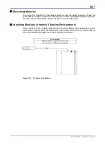
Page 41: ...t the module off the anchor pin at the base Attaching Modules in Intense Vibration Environments If the module is used in intense vibration environments fasten the module with a screw Use screws of typ...

Page 42: ...erve the following precautions a The wiring for the input circuit must be kept as far away as possible from the power supply or grounding circuitry b Twisting the input wire at short equal intervals m...

Page 43: ...n in Figure A4 6 Figure A4 6 Surge Suppressor If you configure an output terminal as an open collector and have it drive an auxiliary relay or other inductive load install a surge suppressor as descri...

Page 44: ...for F3CU04 0S Figure A4 7 Terminal Wiring Diagram No wire must be connected to the terminals marked NC in the terminal assignment diagram or terminal wiring diagram Otherwise the module will not funct...

Page 45: ...al Wiring Example for F3CU04 0S The output terminals of F3CU04 0S are open collector only Figure A4 8 Wiring Example for Connecting a Relay Figure A4 9 Wiring Example for Connecting an SSR CAUTION Rea...

Page 46: ...Terminal Assignment Diagram for F3CU04 1S For thermocouple and DC voltage input For RTD input Figure A4 10 Terminal Wiring Diagram No wire must be connected to the terminals marked NC in the terminal...

Page 47: ...output type selected Figure A4 11 Output Terminal Wiring Diagram for F3CU04 1S If F3CU04 1S is used for current output to drive an external load with the OUTPUT parameter set to Analog ensure that th...

Page 48: ...by software Figure A4 12 Wiring Example for Connecting an SCR analog output Figure A4 13 Wiring Example for Connecting a Relay open collector output Figure A4 14 Wiring Example for Connecting an SSR...

Page 49: ...ng On B2 Types of Relays and Registers B2 1 Types of Relays B2 2 Types of Registers B2 3 How to Enable Settings B2 4 How to Back up Set Points to EEPROM B2 5 Initializing All Settings B3 Setup and Ope...

Page 50: ...Blank Page...

Page 51: ...ns when reading from or writing to the module from a CPU For details on the relays and registers provided with this module see Chapter B2 Types of Relays and Registers Content See Accessing from a CPU...

Page 52: ...and reading from input relays Reading Registers READ HRD Use the Read instruction or High Speed Read instruction for reading registers Reading is performed in 16 bit units Table B1 1 Reading Register...

Page 53: ...he specified area Writing is performed in 16 bit units Table B1 2 Writing to Registers Function No Instruction Mnemonic Symbol Is Input condition Required Execution Condition Step count Processing uni...

Page 54: ...slot number where the module is installed Figure B1 1 Reading Relays TIP This module is provided with an interrupt function for use with BASIC CPUs and other non sequence CPUs As the interrupt functio...

Page 55: ...OFORMAT I SL Slot number n Data position number I Output variable name storing data to be written Writes output variable I to data position number n of the module installed in slot SL If the data posi...

Page 56: ...On After power on it takes up to approximately 2 seconds for the module startup to complete startup initialization Any data written during this period may be ignored For instance if a write instructi...

Page 57: ...the cascade control mode 3 Denotes that self diagnostics has detected a burnout AD converter error or other errors which prohibits normal operation Table B2 1 List of Input Relays 2 2 Input Relay Num...

Page 58: ...tput and other operation control parameters B2 2 9 I O parameters I O type settings Use these parameters to select input and output types for individual loops These are the most basic loop specific pa...

Page 59: ...es not affect module operation If the register is read after the write operation however the written value or a register specific value may be returned The register specific value may or may not be a...

Page 60: ...H RO C4 12 CSP 2 RO 13 CSP 3 RO 14 CSP 4 RO Control output 21 HOUT 1 Control output OL to OH for single output 0 to OH for heating cooling output RO C2 C7 1 22 HOUT 2 RO 23 HOUT 3 RO 24 HOUT 4 RO Cool...

Page 61: ...efault Value Attribute Stored See Also Loop 1 Loop 2 Loop 3 Loop 4 61 AOUT1 Output preset value 500 to 10500 5 00 to 105 00 0 RW C2 5 62 AOUT2 0 RW 63 AOUT3 0 RW 64 AOUT4 0 RW 65 AOUT5 0 RW 66 AOUT6 0...

Page 62: ...basic setup elements The module also initializes I O parameters and operation parameters based on the controller parameter values 4 Enable I O type settings Enables the Input Type Selection parameter...

Page 63: ...ounter reaches its maximum limit subsequent write to EEPROM executions are no longer counted although they can still be executed until the EPPROM actually fails Table B2 9 SP Value Backup Operation Pa...

Page 64: ...alue set with the power frequency selector switch SW1 2 It can also be selected with SW1 2 For details on how to do so see Section A4 1 Selecting Input Types and Power Frequency If the power frequency...

Page 65: ...a Range Terminal 15 8 7 6 5 4 3 2 1 0 87 OUTPUT Output type selection 1 0 Open collector output default 1 Analog output 2 3 4 5 6 7 8 Note Setting a bit to 1 or 0 sets the corresponding terminal to an...

Page 66: ...5 of PRL to PRH RO 103 303 503 703 CSP Control set point Industrial unit PRL to PRH RO C4 104 304 504 704 HOUT Control output OL to OH for single output 0 to OH for heating cooling output RO C2 C7 1 1...

Page 67: ...V OVER 14 15 FUNC ERR 1 Error detected Alarm Status Table B2 14 Alarm Status ALM STUS Bit pos Symbol Description 15 14 13 12 11 10 9 8 7 6 5 4 3 2 1 0 0 ALM1 Alarm 1 generated 1 ALM2 Alarm 2 generated...

Page 68: ...put selection None 0 Normal output 1 External output 0 RW C2 6 127 327 527 727 AT Start Auto tuning None 0 AT stop 1 5 AT start reverts to 0 when AT stops 0 RW C5 2 128 328 528 728 SPNO SP number sele...

Page 69: ...ype Selection RW C3 1 1 To select input type by software you must set the input type selector switches to set by software that is SW5 0 and SW1 4 OFF also see Section A4 1 Selecting Input Types and Po...

Page 70: ...for even numbered loops in two input changeover mode with a maximum resolution of 14 bits 16384 SH RW C3 4 352 752 PRL PV range lower limit SL RW 353 753 PDP PV range decimal point position None 0 to...

Page 71: ...cutions exceeds the maximum limit of 100 000 EEPROM may fail and subsequent storing is not guaranteed Therefore in situations where stored parameters are frequently updated you should always disable t...

Page 72: ...574 774 Y1 Broken line bias 1 Industrial SH SL to SH SL 0 RW 175 375 575 775 X2 Broken line input 2 Industrial 5 0 to 105 0 of SL to SH SL RW 176 376 576 776 Y2 Broken line bias 2 Industrial SH SL to...

Page 73: ...8 Deviation range 11 Upper limit with waiting 12 Lower limit with waiting 13 Upper deviation limit with waiting 14 Lower deviation limit with waiting 17 Upper lower deviation limit with waiting 18 De...

Page 74: ...0 to 1050 5 0 to 105 0 0 RW Irregular You need to execute a specific procedure every time to update stored set point values Table B2 24 PID Parameters 2 4 Data Position Number Symbol Description Unit...

Page 75: ...fault Value Attribute Stored See Also Loop1 Loop2 Loop3 Loop4 261 461 661 861 4 SP Set point Industrial PRL to PRH PRL RW Irregular B2 4 C4 1 262 462 662 862 4 A1 Alarm 1 preset value Industrial 30000...

Page 76: ...instruction operand 1 Enable setup instruction operand 0 RW 72 OPE Setup Instruction Operand 1 2 4 8 16 See Table B2 27 for details 0 RW 73 STUS Setup Instruction Response 0 No error Data position nu...

Page 77: ...before transiting to Setup mode generates an error and returns an error value of 32767 in the STUS register Always finishing enabling all required settings always set SETUP to 0 Disable setup instruc...

Page 78: ...top mode and Automatic mode Setup instruction Transition from normal operation to Setup mode Writing a value of 1 to the Setup register initiates a transition to Setup mode When the transition complet...

Page 79: ...as the setup process begins It then resets the OPE register to 0 initializes the related parameters writes the exit status to the STUS register and finally turns on the CMDRDY relay upon setup comple...

Page 80: ...ill be ignored Sample Program for Setting Controller and I O parameters The sample program shown below writes a list of controller and I O parameters sequentially on the rising edge of I00001 It disab...

Page 81: ...nput type selection for loop4 DC voltage 0 5 V I O type settings RL and RH for loop1 0 C for RL 1000 C for RH input range settings RL and RH for loop2 0 C for RL 500 C for RH input range settings RL a...

Page 82: ...B2 26 IM 34M06H62 02E 2nd Edition June 2008 00 Figure B2 4 Sample Program for Setting Controller and I O Parameters 2 6...

Page 83: ...B2 27 IM 34M06H62 02E 2nd Edition June 2008 00 Figure B2 4 Sample Program for Setting Controller and I O Parameters 3 6...

Page 84: ...B2 28 IM 34M06H62 02E 2nd Edition June 2008 00 Figure B2 4 Sample Program for Setting Controller and I O Parameters 4 6...

Page 85: ...B2 29 IM 34M06H62 02E 2nd Edition June 2008 00 Figure B2 4 Sample Program for Setting Controller and I O Parameters 5 6...

Page 86: ...B2 30 IM 34M06H62 02E 2nd Edition June 2008 00 Figure B2 4 Sample Program for Setting Controller and I O Parameters 6 6...

Page 87: ...kup 0 RW 77 and 78 long word EEP CNTR EEPROM write counter Times 1 to 100 000 RO 201 401 601 801 1 SP Set point Industrial PRL to PRH PRL RW Irregular 221 421 621 821 2 SP Set point Industrial PRL to...

Page 88: ...lay SPWR R input relay X 32 WR 1 0 0 0 0 Write SP to EEPROM process Writing Waiting for completion Ready to write Ready to write Write SP values SP data position number 201 Figure B2 5 Procedure for W...

Page 89: ...n relay I00102 turns on it rewrites the SP value and at the same time backs up all SP values to the EEPROM Figure B2 6 Sample Program for Writing SP Values to EEPROM B2 5 Initializing All Settings To...

Page 90: ...Blank Page...

Page 91: ...procedure flow from setup to operation Updating a parameter may inadvertently affect initialize other parameters and thus it is important that you perform setup in the sequence described above Sectio...

Page 92: ...er frequency selection 1 None 0 50Hz 1 60Hz 0 RW 1 C3 2 1 The power frequency can also be selected using a hardware switch For details on how to do so see Section A4 1 Selecting Input Types and Power...

Page 93: ...s 1 and 2 or loops 3 and 4 Only the parameters of loop 2 and 4 are used in control operation The description from Section B3 2 Setting I O Parameters to Section B3 4 Operation assumes the use of the s...

Page 94: ...on Relationship between Controller Mode Preset Value and Loop Odd numbered Loop Loop 1 or 3 Even numbered Loop Loop 2 or 4 MD12 MD34 Controller mode 0 Two single loops Single loop Single loop 1 Two in...

Page 95: ...ble only with F3CU04 1S which supports continuous output It specifies output type for each output terminal See also Table B3 7 2 For F3CU04 0S which has only four output terminals neither registers OU...

Page 96: ...Sample Program for Setting Controller Parameters This section shows a sample program for setting controller parameters The program sets the power supply to 60Hz and disables loops 3 and 4 Figure B3 2...

Page 97: ...B3 7 IM 34M06H62 02E 2nd Edition June 2008 00 Figure B3 2 Sample Program for Setting Controller Parameters 2 2...

Page 98: ...lection These parameters specify the input type of individual loops Select a preset value that matches the temperature range and voltage range of the sensor to be used Table B3 8 Input Type Selection...

Page 99: ...2 3 Sample Program for Setting I O Parameters This section shows a sample program for setting I O parameters The program sets the input types followed by the input ranges for loops 1 and 2 Figure B3...

Page 100: ...B3 10 IM 34M06H62 02E 2nd Edition June 2008 00 Figure B3 3 Sample Program for Setting I O Parameters 2 3...

Page 101: ...B3 11 IM 34M06H62 02E 2nd Edition June 2008 00 Figure B3 3 Sample Program for Setting I O Parameters 3 3...

Page 102: ...time and derivative time are automatically determined and set To enter dynamic auto tuning mode set the Dynamic Auto tuning Enable SELF parameter to 1 enabled as shown in Table B3 10 When SELF is set...

Page 103: ...rocedure every time to update stored set point values Otherwise stored set points will not be updated so the parameters revert to their last stored values whenever the module is turned off and then on...

Page 104: ...l Description Unit Data Range Default Value Attribute Stored See Also Loop 1 Loop 2 Loop 3 Loop 4 201 401 601 801 1 SP Set point Industrial unit PRL to PRH PRL RW C4 1 206 406 606 806 1 PB Proportiona...

Page 105: ...e Also Loop 1 Loop 2 Loop 3 Loop 4 X04 X12 X20 X28 AT RDY Auto tuning completed 0 AT in progress 1 AT completed C5 2 1 denotes the slot number where the module is installed Set the set point to be use...

Page 106: ...meters before operation parameters Setting Operation Parameters for Dynamic Auto tuning The following is a sample program for setting operation parameters for dynamic auto tuning The program enables d...

Page 107: ...The following is a sample program for setting operation parameters for PID control It specifies a set point and sets Run Stop Auto tuning Enable and other operation control parameters essential for m...

Page 108: ...lection None 0 Automatic 1 Manual 2 Cascade only valid for the even numbered loop in cascade control mode 0 RW C7 2 C7 4 124 324 524 724 RMT LOC Remote local selection None 0 Local 1 Remote 0 RW C7 3...

Page 109: ...this program are stored internally in the module and thus do not need to be setup after each power up These relays therefore need to be operated only when the module is replaced or when parameter valu...

Page 110: ...B4 2 IM 34M06H62 02E 2nd Edition June 2008 00 Figure B4 1 Sample Program Component for Setting Setup Parameters 2 5...

Page 111: ...B4 3 IM 34M06H62 02E 2nd Edition June 2008 00 Figure B4 1 Sample Program Component for Setting Setup Parameters 3 5...

Page 112: ...B4 4 IM 34M06H62 02E 2nd Edition June 2008 00 Figure B4 1 Sample Program Component for Setting Setup Parameters 4 5...

Page 113: ...B4 5 IM 34M06H62 02E 2nd Edition June 2008 00 Figure B4 1 Sample Program Component for Setting Setup Parameters 5 5...

Page 114: ...B4 6 IM 34M06H62 02E 2nd Edition June 2008 00 Figure B4 2 Sample Program Component for Operation Parameter Setup and Operation Control 1 3...

Page 115: ...B4 7 IM 34M06H62 02E 2nd Edition June 2008 00 Figure B4 2 Sample Program Component for Operation Parameter Setup and Operation Control 2 3...

Page 116: ...B4 8 IM 34M06H62 02E 2nd Edition June 2008 00 Figure B4 2 Sample Program Component for Operation Parameter Setup and Operation Control 3 3...

Page 117: ...related functions C4 SP related Functions Describes set point SP limiter and other SP related functions C5 Auto tuning Function Describes the Dynamic Auto tuning and the normal Auto tuning function C6...

Page 118: ...Blank Page...

Page 119: ...oller Loops are Used according to the Controller Mode Setting Symbol Description How Loops are Used Odd numbered Loop 1 or 3 Even numbered Loop 2 or 4 MD12 MD34 Controller Mode 0 Two single loops Sing...

Page 120: ...ormal output EXOUT OUT EXOUT is not available in the heating cooling control mode EXOUT Input register I O register Terminal Local Remote MOUT MOUTC Heating cooling computation POUTC C6 Control and Co...

Page 121: ...The controller mode must be set to Cascade Control before Automatic Manual Cascade Selection A M C can be set to 2 Cascade In cascade control mode operation proceeds according to the setup for the eve...

Page 122: ...4 form a cascaded loop In cascade control mode parameters of the even numbered controller loop 2 or 4 are used for run stop and other operations This flowchart illustrates the module functions as fun...

Page 123: ...l cooling output 0 to OL 0 RW 336 736 EXOUT External output 5 0 to 105 0 0 RW C2 6 1 The controller mode must be set to Cascade Control before Automatic Manual Cascade Selection A M C can be set to 2...

Page 124: ...1 5 Control Set Point and Control Output in Various Operating Status Operating Status Primary Loop Secondary Loop RUN STP A M C Control Output Control Set Point Control Output Cooling Control Output S...

Page 125: ...l output of the primary loop follows the control set point of the secondary loop tracking function Secondary Loop In cascade control mode the control output from the primary loop is used as the contro...

Page 126: ...and 2 or a pair of controller loops 3 and 4 is used to control a single target through changeover between the two PVs This flowchart illustrates the module functions as functional blocks Some details...

Page 127: ...g output 0 to OL 0 RW 336 736 EXOUT External output 5 0 to 105 0 0 RW C2 6 361 761 SELMD Two input changeover mode None 0 Automatic changeover using temperature range 1 Automatic changeover using uppe...

Page 128: ...itations See Also C3 PV related Functions C4 SP related Functions C2 Output related Functions PV Range Setting Setting the PV range for two input changeover control requires special attention First se...

Page 129: ...d parameter of a disabled loop is changed the new parameter value is stored For a disabled loop no input computation PID computation or output computation is performed no input or output values are up...

Page 130: ...Blank Page...

Page 131: ...d parameters and perform output operation The functions are broadly classified into two groups output control and output terminal selection Output control functions set up parameters that affect the c...

Page 132: ...T 4 HOUT 3 HOUT 2 HOUT 1 Output terminal selection C2 5 Analog Output m denotes a PID number between 1 and 4 HOUT R n COUT R n HOUT R 1 COUT R 1 HOUT R 2 HOUT R 3 HOUT R 4 COUT R 2 COUT R 3 COUT R 4 I...

Page 133: ...tput limit 5 0 to 105 0 if OL OH OL is always output if OL OH 1000 RW C2 4 2 230 430 630 830 2 OL Lower output limit 0 or 1000 for heating cooling control RW 232 432 632 832 2 HYS ON OFF control hyste...

Page 134: ...OH Upper output limit 5 0 to 105 0 if OL OH OL is always output if OL OH 1000 RW C2 4 2 C6 3 270 470 670 870 4 OL Lower output limit 0 or 1000 for heating cooling control RW 272 472 672 872 4 HYS ON O...

Page 135: ...ust be enabled to take effect For details on how to enable settings see Section B2 3 How to Enable Settings C2 2 Output Type Selection The Output Type Selection OUTPUT parameter available only with F3...

Page 136: ...ters for F3CU04 1S Data Position Number Symbol Description Default Value Relationship between Setting and Output 91 OUTSEL1 Output terminal 1 1 1 HOUT 1 21 AOUT1 2 HOUT 2 22 AOUT2 3 HOUT 3 23 AOUT3 4...

Page 137: ...op4 X05 X13 X21 X29 HOUT R Heating control output 0 OFF 1 ON 1 denotes the slot number where the module is mounted The hysteresis parameters specify the minimum deviation of the PV from the control se...

Page 138: ...ion In Manual mode you can control the ON OFF output manually by writing 100 0 or 0 0 to the Manual Output MOUT parameter TIP If you set MOUT to a value smaller than 0 0 the value is treated as 0 0 If...

Page 139: ...of the cycle time In heating cooling control operation the PID computation result COUT is output after it is converted to ON OFF duty cycle as defined by the Cooling Cycle Time CTc parameter Table C2...

Page 140: ...t OL to OH for single output 0 to OH for heating cooling output RO Continuous PID control is available only with F3CU04 1S TIP Time proportional PID control output and continuous PID control output di...

Page 141: ...05 0 if OL OH OL is always output if OL OH 1000 RW 210 410 610 810 1 OL Lower output limit 0 RW 229 429 629 829 2 OH Upper output limit 5 0 to 105 0 if OL OH OL is always output if OL OH 1000 RW 230 4...

Page 142: ...duration of 50 s Figure C2 6 Rate of change Limit Table C2 12 Rate of change Limit Parameter Data Position Number Symbol Description Unit Data Range Default Value Attribute Stored Loop 1 Loop 2 Loop...

Page 143: ...ating and cooling outputs are generated in the dead band If the heating and cooling capacities of a process differ you can define a cooling gain to balance the heating and cooling control loop gains F...

Page 144: ...631 831 2 MR Manual reset value 5 0 to 105 0 500 RW 234 434 634 834 2 GAIN C Cooling gain 1 to 999 1 to 999 100 RW 236 436 636 836 2 DB Dead band Industrial unit PID control 10 0 to 10 0 of PRH PRL O...

Page 145: ...5 0 to 105 0 0 RW 278 478 678 878 4 POUT C Cooling preset output 50 to 1050 5 0 to 105 0 0 RW The rate of change limit is disabled in heating cooling PID control Table C2 14 Input Relays Related to He...

Page 146: ...for P control Table C2 15 Dead Band in Heating Cooling PID Control Data Position Number Symbol Description Unit Data Range Default Value Attribute Stored Loop 1 Loop 2 Loop 3 Loop 4 216 416 616 816 1...

Page 147: ...proportional band for cooling output is adjusted using the cooling gain as follows Proportional band for heating output Proportional band Proportional band for cooling output Proportional band coolin...

Page 148: ...ng PID Control Data Position Number Symbol Description Unit Data Range Default Value Attribute Stored Loop 1 Loop 2 Loop 3 Loop 4 214 414 614 814 1 GAIN C Cooling gain 1 to 999 1 to 999 100 RW 234 434...

Page 149: ...d to Automatic mode bump less control without sudden change in output begins However if the cooling output is less than the Lower Output Limit OL because of a small cooling gain setting the cooling ou...

Page 150: ...269 469 669 869 4 OH Upper output limit 0 to 1050 0 0 to 105 0 1000 RW 270 470 670 870 4 OL Lower output limit 1000 RW In Automatic mode depending on the dead band and cooling gain preset values somet...

Page 151: ...r cooling output is either 0 or 100 You can specify a dead band around the CSP for turning on the heating and cooling outputs You can also specify a hysteresis for on off or off on transitions in the...

Page 152: ...PRL 0 RW 252 452 652 852 3 HYS ON OFF control hysteresis Industrial unit 0 to PRH PRL PRH PRL x 0 5 RW 255 455 655 855 3 HYS C Cooling ON OFF control hysteresis Industrial unit 0 to PRH PRL PRH PRL x...

Page 153: ...nuous Current Output Table C2 21 Parameters Related to Analog Output 1 2 Data Position Number Symbol Description Unit Data Range Default Value Attribute Stored Loop 1 Loop 2 Loop 3 Loop 4 61 AOUT1 Out...

Page 154: ...EXOUT is not constrained by the upper or lower output limit As an example a sequence CPU may read the value of HOUT correct or otherwise process the value and then write the processed value to EXOUT...

Page 155: ...C3 1 IM 34M06H62 02E 2nd Edition June 2008 00 C3 PV related Functions PV related functions are used to set up and control inputs...

Page 156: ...3 11 Two input changeover PRH e PRL e PDP e SL n RL n RJC n MD12 SELH e SELL e Two input changeover PV range SELMD e MD34 o here denotes an odd channel num ber where o is 1 or 3 e here denotes an even...

Page 157: ...350 550 750 BSL Burnout selection for thermocouple or RTD input None 0 OFF 1 Up Scale 2 Down Scale 1 RW C3 5 351 751 PRH PV range upper limit Industrial unit 30000 to 30000 0 PRH PRL 30000 Changeable...

Page 158: ...Frequency Table C3 2 Input Type Selection Parameter Data Position Number Symbol Description Unit Data Range Default Value Attribute Stored Loop 1 Loop 2 Loop 3 Loop 4 142 342 542 742 IN Input type se...

Page 159: ...2300 Platinel 2 0 0 to 1390 0 C F OFF 15 0F 0 13900 1 0 13900 ON 47 2F 0 1390 0 0 1390 RTD JPt100 200 0 to 500 0 C 0 ON OFF 16 10 2000 5000 1 2000 5000 ON 48 30 200 500 0 200 500 200 0 to 200 0 C 1 OF...

Page 160: ...2 32 0 to 2534 0 F F OFF 15 0F 320 25340 1 320 25340 ON 47 2F 32 2534 0 32 2534 RTD JPt100 328 0 to 932 0 F 0 ON OFF 16 10 3280 9320 1 3280 9320 ON 48 30 328 932 0 328 932 328 0 to 392 0 F 1 OFF 17 1...

Page 161: ...C3 4 Power Frequency Parameter Data Position Number Symbol Description Unit Data Range Default Value Attribute Stored Loop 1 Loop 2 Loop 3 Loop 4 81 FREQ Power frequency selection 1 None 0 50 Hz 1 60...

Page 162: ...e measured Note For temperature input scaling uppler and lower limits SH SL are fixed at the input range upper and lower limits RH RL respectively Figure C3 2 Examples of Input Range Setting As shown...

Page 163: ...g Table C3 6 PV Range Parameters Data Position Number Symbol Description Unit Data Range Default Value Attribute Stored Loop 1 Loop 2 Loop 3 Loop 4 101 301 501 701 PVIN Input process value Industrial...

Page 164: ...Burnout related Parameters Data Position Number Symbol Description Unit Data Range Default Value Attribute Stored Loop 1 Loop 2 Loop 3 Loop 4 41 42 43 44 RUN STUS Operating status None On off for indi...

Page 165: ...the temperature of the terminal block of the module is automatically measured and used for reference junction compensation in the thermocouple temperature measurement If an external reference point d...

Page 166: ...roken line bias added X2 X3 Figure C3 4 Broken line Biasing Example Table C3 11 Broken line Biasing Parameters Data Position Number Symbol Description Unit Data Range Default Value Attribute Stored Lo...

Page 167: ...nace is indirectly determined by measuring the ambient temperature in the furnace where a fixed bias is added to the ambient temperature to represent the temperature of the material The function is al...

Page 168: ...are root extraction does not apply to any input below low cut point where output input Slope 1 Input Output Figure C3 5 Square Root Extraction Example Table C3 13 Square Root Extraction Parameters Dat...

Page 169: ...nput filtering making the module less responsive to changes in the input signal Thus the Input Filter parameter should be set to the minimum required value see Figure C3 6 The input filter performs 1s...

Page 170: ...SELH changeover occurs with respect to SELH PRL 1 RW 363 763 SELL Two input changeover lower limit PRL RW 323 723 INSEL Input selection None 0 Input 1 1 Input 2 0 RW Automatic Changeover Using Tempera...

Page 171: ...llows INSEL 0 Input 1 is selected INSEL 1 Input 2 is selected The PV may change abruptly when changeover is made between Input 1 and Input 2 as illustrated below 1 0 Input 2 Input 1 PV INSEL 0 Figure...

Page 172: ...t and normal input An external input may also be used for testing without a thermocouple or sensor connected Table C3 16 External Input Parameters Data Position Number Symbol Description Unit Data Ran...

Page 173: ...P Related Functions This chapter describes the selection of the set points used in control and computation functions as well as changes in set point value accompanied by a change in operation control...

Page 174: ...tion Method Table C4 1 SP related Parameters Data Position Number Symbol Description Unit Data Range Default Value Attribute Stored Loop1 Loop2 Loop3 Loop4 103 303 503 703 CSP Control set point Indust...

Page 175: ...Value TIP If the Zone PID Selection ZONE parameter is set to 0 Disabled changing the SP Number Selection SPNO also changes the PID constants including PB TI and TD For details on the parameters that a...

Page 176: ...n Number Symbol Description Unit Data Range Default Value Attribute Stored Loop1 Loop2 Loop3 Loop4 103 303 503 703 CSP Control set point Industrial unit PRL to PRH RO 164 364 564 764 SPH Upper SP limi...

Page 177: ...SP gradient function acts so that the process value PV approaches the control set point at the specified gradient This function is called PV tracking It is disabled when burnout is detected For detail...

Page 178: ...nce between 2 SP and 1 SP is 140 C and it is desired to achieve this temperature change in 2 minutes Hence SPR UP is set to 70 C minute 70 C minute SPR UP 140 2 70 C minute Duration for temperature ri...

Page 179: ...g function changes the CSP gradually according to the SP gradient setting from the value designated by the old SP number to the value designated by the new SP number Figure C4 4 PV Tracking Operation...

Page 180: ...d from Remote to Local When the Automatic Manual Cascade Selection A M C parameter of a secondary loop in cascade control is changed from Cascade to Automatic or Manual Figure C4 5 SP Tracking Operati...

Page 181: ...amic auto tuning set the Dynamic auto tuning Enable SELF parameter to 1 Enabled The following PID values are updated by dynamic auto tuning Proportional Band PB Integral Time TI and Derivative Time TD...

Page 182: ...PID parameters automatically when PID values are calculated In situations where this is undesirable set the Dynamic auto tuning Enable SELF parameter to 0 Disabled Dynamic auto tuning should not be us...

Page 183: ...r When the PV reaches the third peak as shown in Figure C5 2 the PID constants are calculated stored and auto tuning ends Figure C5 2 Auto tuning Function If the Output Type Selection OUTPUT is set to...

Page 184: ...the Auto tuning Completed AT RDY input relay and the Auto tuning Status AT STUS I O register The AT RDY input relay is 1 when the Start Auto Tuning AT relay is 0 and it is 0 when the AT relay is set t...

Page 185: ...ints are limited within 3 to 97 of the input range The upper and lower range limits are RH and RL for thermocouple and RTD input SH and SL for direct voltage input and PRH and PRL for two input change...

Page 186: ...er Symbol Description Unit Data Range DefaultValue Attribute Stored Loop1 Loop2 Loop3 Loop4 127 327 527 727 AT Start auto tuning None 0 Stop AT 1 5 Start AT reverts to zero when auto tuning completes...

Page 187: ...w PV Maximum High PV 0 PV 100 ON Current increases On time increases ON Current increases On time increases OFF Current decreases On time reduces Output value Increases Decreases PV CSP PV CSP PV CSP...

Page 188: ...iation that will produce a 100 change in the control output where the percentage change in input is deemed to be 100 if the PV value changes from PRL to PRH Defining a smaller proportional band produc...

Page 189: ...t eliminate the offset Adjusting the Integral Time TI and Manual Reset MR parameters may however eliminate the offset Figure C6 4 Adjusting the Proportional Band Table C6 2 Proportional Band Parameter...

Page 190: ...nge that a proportional action alone would produce given a stepped deviation The longer the integral time the slower will be the output change Conversely the shorter the integral time the faster will...

Page 191: ...the following points Adjust MR so as to reduce the offset Adjust MR so that it does not produce an offset in the opposite direction A manual reset value that is too large will produce an offset in th...

Page 192: ...viation whether increasing or decreasing and trigger appropriate corrective action earlier The derivative action D action changes the output proportionally to the gradient rate of change of the deviat...

Page 193: ...for fast response inputs such as pressure or flow rate or inputs that are inherently oscillating such as an optical sensor If the derivative time TD is too long short cycle oscillations will appear i...

Page 194: ...If possible use auto tuning Otherwise do the following 2 Adjust PB TI and TD in this order Change the values gradually whilst checking and writing down the result 3 Start with a large PB and decrease...

Page 195: ...SP is changed Local Remote or Cascade Local Remote or Cascade Adopt PV derivative type PID in order to quickly bring the PV to an updated CSP The PV derivative type PID control method immediately gene...

Page 196: ...1 Fixed point control 0 RW PV Derivative Type PID Control Method In this PID control method the derivative action acts only on the PV This method is effective to reduce output bumps due to SP change i...

Page 197: ...again enters a range where there is no risk of overshooting the function reverts little by little to the original set point Original CSP Fuzzy logic begins Time Process Value PV PV Supplementary set p...

Page 198: ...r limit and resumed when the deviation falls within the range specified with ARW Here the value of ARW is a percentage of the proportional band PB Thus if ARW is set to 100 PID computation resumes whe...

Page 199: ...None 1 to 4 RO 185 385 585 785 ZONE Zone PID selection None 0 Disabled 1 Enabled 0 RW You can read the Current PID Number PIDNO parameter to confirm the PID number currently selected The PIDNO select...

Page 200: ...r CSPNO parameter and the Current PID Number PIDNO Changing the SPNO also activates the PV tracking function see Section C4 5 PV Tracking Switching from 1 SP to 3 SP Switching from 3 SP to 1 SP Switch...

Page 201: ...n optimal PID values for each of these zones As the PV value moves from the current zone to a different zone the module automatically switches to the PID values assigned to that new zone Input range l...

Page 202: ...m 2 to 1 It also applies when operation is switched from PID parameter group 1 2 or 3 to group 4 according to the Reference Deviation RDV parameter PID 1 Reference point 1 Zone switching hysteresis wi...

Page 203: ...n RDV parameter has priority over switching by the Reference Point 1RP 2RP parameters In addition when the deviation falls below the Reference Deviation RDV operation reverts to using the Zone PID par...

Page 204: ...Blank Page...

Page 205: ...ntrol Output in Stop Mode OT Control Output HOUT Cooling Control Output COUT 0 Preset output POUT 0 1 0 if preset output POUT 0 0 100 0 if POUT 0 1 0 2 Preset output POUT Cooling preset output POUT C...

Page 206: ...to Run Control and computation begins from OL 1 Switching from Stop to Run in Automatic mode when POUT OL OH POUT Control output Time Switching from Stop to Run 2 Switching from Stop to Run in Manual...

Page 207: ...put HOUT COUT values are copied to the manual output MOUT MOUTC registers when switching from Stop mode to Run mode Figure C7 5 Switching to Run Mode in Heating Cooling On Off Control For all control...

Page 208: ...In On Off Control mode only output values of 100 or 0 are allowed For details see paragraph Manual Operation in Section C2 4 1 On Off Control Output In Heating Cooling PID Control mode manual output i...

Page 209: ...s independent of the control output value in Manual mode OFF MOUT Control output Time Switching from Manual to Automatic Turns on because PV CSP 1 Switching from Manual to Automatic in On Off Control...

Page 210: ...to the Remote Set Point RSP parameter is used as the set point For details see Section 4 2 Remote Set Point 4 SP 1 SP 3 SP 2 SP SPNO RMT LOC RSP Local Remote SP number selection Remote local selectio...

Page 211: ...ster of the odd numbered loop 0 0 0 0 0 1 Manual 0 1 0 0 1 0 1 2 Cascade 1 0 1 1 0 1 0 1 By reading the A M input relay for both the odd numbered and even numbered loops you can determine whether a lo...

Page 212: ...ual to CSP2 of the secondary loop beforehand the PID control output from the secondary loop will change smoothly in cascade mode starting with the current output value C7 4 2 Automatic Mode In Automat...

Page 213: ...y loop outputs as control output values OUTPUT2 the values of the manual output MOUT and MOUTC parameters of the even numbered loop The PV2 and CSP2 values of the secondary loop as well as the primary...

Page 214: ...to Preset Output Data Position Number Symbol Description Unit Data Range Default Value Attribute Stored Loop1 Loop2 Loop3 Loop4 217 417 617 817 1 POUT Preset Output 50 to 1050 5 0 to 105 0 0 RW 237 43...

Page 215: ...C8 1 IM 34M06H62 02E 2nd Edition June 2008 00 C8 Alarm Function This chapter describes the alarm function of the module...

Page 216: ...ion using the SP Number Selection SPNO parameter You can also modify the alarm preset value of an alarm during operation Figure C8 1 Block Diagram of Alarm Functions Alarms 3 and 4 have no associated...

Page 217: ...Alarm 1 preset value Industrial unit 30000 to 30000 PRH RW C8 4 263 463 663 863 4 A2 Alarm 2 preset value PRL RW C8 4 264 464 664 864 4 A3 Alarm 3 preset value PRH RW C8 4 265 465 665 865 4 A4 Alarm 4...

Page 218: ...8 4 describes the alarm functions Alarm types 1 8 are without waiting and alarm types 11 18 are with waiting For details on the wait function see Section C8 2 Wait Function Table C8 4 Alarm Functions...

Page 219: ...0 9 8 7 6 5 4 3 2 1 0 0 ALM1 Alarm 1 occurred 1 ALM2 Alarm 2 occurred 2 ALM3 Alarm 3 occurred 3 ALM4 Alarm 4 occurred 4 ALMW1 Alarm 1 waiting 5 ALMW2 Alarm 2 waiting 6 ALMW3 Alarm 3 waiting 7 ALMW4 Al...

Page 220: ...NO Figure C8 2 below shows an example of the alarm function when the alarm type is set to Lower Limit with Waiting Figure C8 2 Operation of the Wait Function TIP After an alarm condition is detected t...

Page 221: ...of four alarm preset values A1 to A4 which can be selected by setting the SP Number SPNO parameter Changing the SP Number changes all the alarm preset values at the same time For details on SP number...

Page 222: ...Blank Page...

Page 223: ...hardware failure may occur and subsequent storage is not guaranteed If stored parameters are updated frequently set NBKUP to 1 no backup to protect the EEPROM In this case stored parameters will not...

Page 224: ...Blank Page...

Page 225: ...C10 1 IM 34M06H62 02E 2nd Edition June 2008 00 C 10 Self diagnosis Function This chapter describes how to identify and rectify problems that may occur at power up or during normal operation...

Page 226: ...op 1 Run 1 AUT MAN 0 Automatic 1 Manual 2 CAS 1 Cascade 3 RMT LOC 0 Local 1 Remote 4 EXPV PV 0 Normal input 1 External Input 5 EXOUT OUT 0 Normal output 1 External Output 6 7 8 B OUT 1 PVIN burnout 9...

Page 227: ...eration 105 Automatic Preset output Manual Normal operation 1 Input type setting Incorrect wiring Have the module repaired Hardware failure 6 RJC error in loop Operation continues with reference junct...

Page 228: ...Blank Page...

Page 229: ...ency and Temperature Unit Selector Switches on the Side of the Module TableC11 1 Temperature Unit Selection Temperature Unit Temperature Unit Selector Switch Remarks C OFF Factory setting F ON Always...

Page 230: ...Blank Page...

Page 231: ...Jul 16 2015 00 PART D describes how to troubleshoot problems related to the module D1 Before Performing Checks D2 Troubleshooting a Specific Problem Temperature Control and PID Module PART D Troubles...

Page 232: ...Blank Page...

Page 233: ...stores many preset values internally Sometimes temporary preset values are written for testing purposes such as during trial runs and program debugging and are left uncorrected They are stored in the...

Page 234: ...Blank Page...

Page 235: ...ollowing error phenomena follow the troubleshooting instructions described in the corresponding text sections given on the following pages 1 Input does not change or fluctuates excessively 2 Any LED i...

Page 236: ...Loop 2 Loop 3 Loop 4 71 SETUP Setup Is SETUP set to 1 It must be set to 0 B2 3 81 FREQ Power frequency selection Is FREQ correctly set to match the frequency of the power supply used It must be corre...

Page 237: ...Is bit 15 set If so check ERR STUS C10 2 109 309 509 709 ALM STUS Alarm status Are any of bits 0 3 set If so check the corresponding alarm type alarm setting and alarm hysteresis C8 1 110 310 510 710...

Page 238: ...ck that the PID parameter values are proper For details on how to start auto tuning see Section C5 2 Auto tuning For details on how to adjust the PID parameters manually see Section C6 5 Manual Adjust...

Page 239: ...er that output is either 0 or 100 in ON OFF control mode If the above measures still fail to solve the problem see 1 Input does not change or fluctuates excessively given in this chapter 5 Excessive o...

Page 240: ...Blank Page...

Page 241: ...s on precautions when accessing the module from a CPU see also Chapter B2 Types of Relays and Registers For Information on See Also Accessing from the sequence CPU B1 1 Accessing Using Sequence Instru...

Page 242: ...Blank Page...

Page 243: ...12 CSP 2 RO 13 CSP 3 RO 14 CSP 4 RO 15 Not used 16 17 18 19 20 21 HOUT 1 Control output RO C2 C7 1 22 HOUT 2 RO 23 HOUT 3 RO 24 HOUT 4 RO 25 Not used 26 27 28 29 30 31 COUT 1 Cooling control output RO...

Page 244: ...EPROM RW B2 4 Table E1 4 Function Control Parameters Data Position Number Symbol Description Attribute Stored See Also Loop 1 Loop 2 Loop 3 Loop 4 75 NBKUP Disable backup function RW C9 76 Not used 77...

Page 245: ...719 120 320 520 720 Table E1 7 Operation Control Parameters Data Position Number Symbol Description Attribute Stored See Also Loop 1 Loop 2 Loop 3 Loop 4 121 321 521 721 RUN STP Run stop selection RW...

Page 246: ...45 345 545 745 DEC P Decimal point position RO 146 346 546 746 SH Scaling upper limit RW 147 347 547 747 SL Scaling lower limit RW 148 348 548 748 SDP Scaling decimal point position RW 149 349 549 749...

Page 247: ...4 774 Y1 Broken line bias 1 RW 175 375 575 775 X2 Broken line input 2 RW 176 376 576 776 Y2 Broken line bias 2 RW 177 377 577 777 X3 Broken line input 3 RW 178 378 578 778 Y3 Broken line bias 3 RW 179...

Page 248: ...4 4 217 417 617 817 1 POUT Preset output RW C7 1 218 418 618 818 1 POUT C Cooling preset output RW 219 419 619 819 Not used 220 420 620 820 221 421 621 821 2 SP Set point RW Irregular B2 4 C4 1 222 42...

Page 249: ...4 4 257 457 657 857 3 POUT Preset output RW C7 1 258 458 658 858 3 POUT C Cooling preset output RW 259 459 659 859 Not used 260 460 660 860 261 461 661 861 4 SP Set point RW Irregular B2 4 C4 1 262 46...

Page 250: ...83 883 AL3 Alarm 3 type RW 284 484 684 884 AL4 Alarm 4 type RW 285 485 685 885 HY1 Alarm 1 hysteresis RW C8 1 286 486 686 886 HY2 Alarm 2 hysteresis RW 287 487 687 887 HY3 Alarm 3 hysteresis RW 288 48...

Page 251: ...E1 12 Alarm Status ALM STUS Bit pos Symbol Description 15 14 13 12 11 10 9 8 7 6 5 4 3 2 1 0 0 ALM1 Alarm 1 generated 1 ALM2 Alarm 2 generated 2 ALM3 Alarm 3 generated 3 ALM4 Alarm 4 generated 4 ALMW1...

Page 252: ...ter whilst RW indicates a register that can be read as well as written A mark in the Stored column indicates that the content of the register is stored and need not be re written to the module after p...

Page 253: ...8 X26 ALM2 R Alarm 2 X03 X11 X19 X27 A M Auto manual B3 4 X04 X12 X20 X28 AT RDY Auto tuning completed C5 2 X05 X13 X21 X29 HOUT R Heating control output C2 4 X06 X14 X22 X30 COUT R Cooling control ou...

Page 254: ...Blank Page...

Page 255: ...d operation C6 1 function control parameter B2 7 H heating cooling ON OFF control C2 21 heating cooling PID control C2 13 I I O parameter B2 13 initializing all settings B2 33 input filter C3 15 input...

Page 256: ...tion response STUS B2 20 setup mode SETUP R B2 22 single loop control C1 2 B3 3 SP gradient setting C4 5 SP limiter C4 4 SP number selection C6 14 SP tracking C4 8 SP related functions C4 1 square roo...

Page 257: ...rections 3rd July 2015 Addition of explanation on compliant with EN61326 2 3 2013 Error corrections For Questions and More Information If you have any questions you can send an E mail to the following...

Page 258: ...Blank Page...

Page 259: ...the original value As a countermeasure when rewriting the set point from the application program please take following processing Sequence CPU module when using F3SP Write the set point WRITE instruct...

Page 260: ...Blank Page...

Reviews: