background image

3.10 Waveform Generation Through PWF 


3.10  Waveform Generation Through PWF 

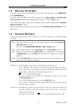
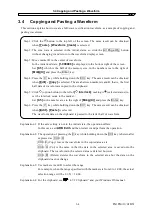
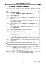
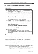
An example using “On-Ph Ctrl Sine” is shown below as an example of waveform generation through 
PWF.  


Step 1:  Click the   button at the top left of the screen. The same result can be obtained 

when 

[Tools]

-

[PWF]

 is selected. 

The screen titled 

[YOKOGAWA ARB Edit - Parameter-Variable Waveform 

Create]

 appears. 

Step 2:  Click the   button to the right of 

[Function]

, and then click 

[On-Ph Ctrl Sine]

 in 

the list. 

Step 3:  Click  the   button  to  the  right  of 

[Parameter-Variable  Waveform]

,  and  then 

click 

[SlopeT]

 in the list. 

Step 4:  Either change the numerical value from 

[10]

 to 

[20]

 in the number input section to 

the right of 

[SlopeT]

 or move the slide bar to the right of 

[Parameter-Variable 

Waveform]

 to change the waveform. 

Step 5:  Click


OK


to close the PWF screen and return to the waveform display screen. 

 
Explanation 1: The PWF screen, the waveform is generated across the entire memory size. 
Explanation 2: Twenty-five different waveforms can be used with PWF. The number of parameters 

to be set depends on the waveform. See “5.5 PWF (Parameter-Variable Waveforms)”.


 “5.5 PWF (Parameter-Variable Waveform)” 


IM FG410-61EN 

3-10 

Summary of Contents for FG410

Page 1: ...User s Manual FG410 FG420 ARBITRARY WAVEFORM EDITOR IM FG410 61EN 3rd Edition ...

Page 2: ...hines Inc Microsoft is a registered trademark of Microsoft Corporation Windows is a trademark of Microsoft Corporation Adobe and Acrobat are trademarks of Adobe Systems Inc Other company or product names are generally trademarks or registered trademarks of the company to which each relates ...

Page 3: ......

Page 4: ...ls are used in this manual Be sure to observe these caution symbols and their contents This mark indicates cautions on handling of this program This manual has the following chapter organization If you are reading this manual for the first time start from 1 OVERVIEW 1 OVERVIEW Presents brief descriptions of the Arbitrary Waveform Editor functions 2 INSTALLATION Describes environmental requirements...

Page 5: ...f this product Be sure to read this information first before using this product All the warnings in the instruction manual must be heeded to prevent hazards that may cause major accidents In case of suspected anomaly If the product controlled by this editor emits smoke an abnormal smell or abnormal noise immediately power it off and stop using it If such an anomaly occurs do not use this product u...

Page 6: ... software is protected under the copyright law of Japan and related international conventions You may either make one copy of this software for backup or storage purposes only or install it onto a hard disk while keeping the original of this software for backup or storage purposes only Reproduction of this instruction manual without permission either in part or in whole is prohibited ABOUT CONTACT...

Page 7: ...Waveform 3 4 3 5 Numerical Expression Waveform 3 5 3 6 Waveform Generation Through Interpolation 3 6 3 7 Compression and Extension of Waveform 1 3 7 3 8 Compression and Extension of Waveform 2 3 8 3 9 Operation Between Waveforms 3 9 3 10 Waveform Generation Through PWF 3 10 4 OPERATIONS ON ARBITRARY WAVEFORM DISPLAY SCREEN 4 1 4 1 Organization and Functions of Waveform Display Screen 4 2 4 2 Tool ...

Page 8: ...3 5 3 1 Control point setting 5 14 5 3 2 Interpolation 5 14 5 3 3 File operation 5 15 5 4 Operation Between Waveforms 5 16 5 4 1 Operation types 5 16 5 4 2 Object of operation 5 16 5 4 3 Operation execution 5 17 5 5 PWF Parameter Variable Waveform 5 18 5 5 1 Waveform selection 5 19 5 5 2 Parameter setting 5 19 5 5 3 PWF parameters 5 19 5 5 4 File operation 5 20 5 5 5 Print 5 21 5 6 Transferring th...

Page 9: ...m Setup Screen Unit Setup 5 23 Figure 5 9 System Setup Screen Waveform memory Setup 5 25 Figure 5 10 System Setup Screen Oscillator Setup 5 27 Figure 7 1 Version Dialog Box 7 2 Table 5 1 Parameters for Standard Waveforms 5 4 Table 5 2 Built in Constants 5 6 Table 5 3 Operators 5 7 Table 5 4 Built in Functions 5 8 Table 5 5 Steady Sine Group 5 19 Table 5 6 Transient Sine Group 5 19 Table 5 7 Pulse ...

Page 10: ...1 OVERVIEW 1 1 General 1 2 1 2 Function Tree 1 2 1 3 Conventions 1 5 ARB Edit 1 1 ...

Page 11: ...rbitrary waveforms by specifying control points using linear interpolation and spline interpolation Generates arbitrary waveforms by using PWF parameter variable waveform Transfer read out function Transfers waveform data and the main parameter settings of the signal generator via USB Reads out the arbitrary waveform data of the signal generator via USB Display function Specifies a range with two ...

Page 12: ...eform Standard Amplitude Selection Waveform Offset Sine Size Triangular Period Square Phase Noise Slope DC Duty Transition Waveform Constant Go to Page Function Y function Enable Disable Page Calculate Page OK All Pages OK Cancel Compress X Axis Start Point Decompress X Axis End Point Decompress to Entire X Axis Y Axis Max Min Max Min Y Axis Amplitude Amplitude Offset Offset Decompress to Max Ampl...

Page 13: ...n OK Cancel PWF File Menu Open Save Select Waveform Print Set Parameters Specify Variable Parameters Slider OK Cancel Setting Menu System Settings System Settings Open Grid Display File Menu Save On Off Print Type Settings Set Type Select Interface Serial Number Unit Settings X Axis Unit Setting Unit Unit Name Minimum Value Setting Maximum Value Setting Y Axis Unit Setting Unit Unit Name Minimum V...

Page 14: ...ing OK Cancel 1 3 Conventions The following conventions are used in this manual Menu names displayed on the screen user input strings and other elements block letters enclosed by square brackets Examples Function s 2 pi Button names displayed on the screen user s key operations and other elements block letters enclosed by a box Examples Cancel OK Alt Press one key while holding down another key Tw...

Page 15: ...1 3 Conventions IM FG410 61EN 1 6 ...

Page 16: ... 2 2 1 1 Personal computer 2 2 2 1 2 USB interface 2 2 2 2 Installation Procedure 2 3 2 2 1 Installing the USB driver software 2 3 2 2 2 Installing Arbitrary Waveform Editor 2 4 2 2 3 Uninstalling Arbitrary Waveform Editor 2 4 IM FG410 61EN 2 1 ...

Page 17: ...512 MB or more recommended Free hard disk space 10 MB or more Display 1024 768 pixels or higher and 256 colors or more OS Windows 8 1 32bit 64bit Microsoft Windows 10 32bit 64bit Microsoft Disk drive CD ROM drive The company and product names are trademarks or registered trademarks of their respective owners The CD ROM drive is required only when the software is installed This software does not su...

Page 18: ...e Engine page User registration must be performed at this time Download VISA Run time Engine Ver 4 6 2 or later 3 The downloaded file is a self extracting file Extract it and install the software 4 The USB driver software is installed when installation is successfully complete For details visit the National Instruments Corporation website After installing the USB driver software connect the device...

Page 19: ...n d When installation has been completed the Arbitrary Waveform Editor can be executed To run the software click the Start button and on the Start menu that appears click ARB_Edit under YOKOGAWA 2 2 3 Uninstalling Arbitrary Waveform Editor On Windows 8 1 click Programs and Features in Control Panel On Windows 10 click Programs and Features in Control Panel under Windows System To remove the ARB Ed...

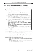
Page 20: ... and Pasting a Waveform 3 4 3 5 Numerical Expression Waveform 3 5 3 6 Waveform Generation Through Interpolation 3 6 3 7 Compression and Extension of Waveform 1 3 7 3 8 Compression and Extension of Waveform 2 3 8 3 9 Operation Between Waveforms 3 9 3 10 Waveform Generation Through PWF 3 10 IM FG410 61EN 3 1 ...

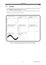
Page 21: ...y operating the software The following conventions are used in this chapter 3 3 Standard Waveform 3 4 Copying and Pasting a Waveform 3 5 Numerical Expression Waveform 3 6 Waveform Generation Through Interpolation 3 7 Compression and Extension of Waveform 1 3 8 Compression and Extension of Waveform 2 3 9 Operation Between Waveforms 3 10 Waveform Generation Through PWF Figure 3 1 Examples of Wavefor...

Page 22: ...nge the numerical value from 50 to 30 in the number input section to the right of Symmetry and press the Enter key This specifies a triangle wave with 30 symmetry Step 4 Clicking All Page OK closes the waveform generation screen and returns to the screen where the waveform is displayed Explanation 1 In this example the waveform is generated across the memory size In the ARB Edit the waveform can b...

Page 23: ...ng it selected status to set the interlock mode to the marker Set 0 5 in the number area to the right of MrkA X and press the Enter key Step 6 Press the V key while holding down the Ctrl key The same result can be obtained when Edit Paste is selected The waveform data on the clipboard is pasted to the latter half of waveform Explanation 1 If the axis setting is not in the initial state the operati...

Page 24: ...OK button to return to the waveform display screen Step 6 Click the button at the left top of the screen Step 7 Click the button to the right of Function and click Waveform Function from the displayed list Step 8 Input s 2 pi in the input area to the right of Constant Input sin x s sin x s 3 3 sin x s 5 5 in the input area to the right of Y Step 9 Click the Compute button The calculated waveform i...

Page 25: ...te is selected The screen titled YOKOGAWA ARB Edit Interpolate appears Step 5 Click the cell for the Y value next to X which shows 0 5 on the list of the control points input 1 and press the Enter key Step 6 Click the Cont Spline button The interpolated waveform is displayed on the waveform display screen If the waveform is hidden behind the interpolation editing screen and difficult to see move t...

Page 26: ...eave the number area to the right of Start X as 0 0 Set the quarter of memory size 0 25 in the number area to the right of End X and press the Enter key The four sine waves displayed across the waveform are contracted to the first quarter on the waveform display screen If the waveform is hidden behind the contraction extraction screen and difficult to see move the screen Step 4 Click the OK button...

Page 27: ...o return to the waveform display screen Explanation 1 It is also possible to vertically contract or move the waveform by specifying the maximum and minimum numerical values at step 4 If the positive and negative full scales are exceeded as a result of extension or move the waveform is clipped to the positive and negative full scales Explanation 2 It is possible to contract extract part of a wavefo...

Page 28: ... to 0 4 Click the Page OK button to return to the inter waveform operation screen Step 5 When the button is clicked the waveform created as a result of addition of the sine wave and noise is displayed in the waveform display area to the right of the screen Step 6 Click the OK button to return to the waveform display screen The waveform superposing noise over the sine wave is now created Explanatio...

Page 29: ...he button to the right of Parameter Variable Waveform and then click SlopeT in the list Step 4 Either change the numerical value from 10 to 20 in the number input section to the right of SlopeT or move the slide bar to the right of Parameter Variable Waveform to change the waveform Step 5 Click OK to close the PWF screen and return to the waveform display screen Explanation 1 The PWF screen the wa...

Page 30: ... Horizontal zoom 4 5 4 5 3 Scrolling 4 5 4 5 4 Marker and range selection 4 5 4 5 5 Marker operations 4 6 4 5 6 Range selection 4 7 4 6 File Operations and Printing 4 9 4 6 1 File types 4 9 4 6 2 New 4 9 4 6 3 Specialized format file 4 10 4 6 4 Text file 4 10 4 6 5 Print 4 12 4 7 Copy and Paste 4 13 4 7 1 Edit operation 4 13 4 7 2 Clipboard 4 13 IM FG410 61EN 4 1 ...

Page 31: ... operation methods and other information on title bar buttons see the Windows manual The menu bar has a pull down menu Clicking a menu name displays the menu options Clicking an option executes that function Otherwise pressing the Alt key and pressing the key for the underlined alphabetic character to the right of the menu name displays the options for the menu for example Alt F displays the optio...

Page 32: ...lined alphabetic character is displayed to the right of the item name on the toolbar or in the waveform display area pressing the underlined alphabetic character while holding down the Alt key selects the corresponding item For example Alt H pressing the H key while holding down the Alt key selects Horiz Zoom Note that Alt H pressing the Alt key and then pressing the H key displays the Help menu o...

Page 33: ...area Selecting Setup Setup Alt S S opens the system setup screen On the system setup screen it is possible to select the signal generator model set or transfer main parameters transfer waveform data set the display unit or perform other operations See 5 6 Transferring the Waveform and Settings Each time Setup Show Grid Alt S G is selected the grid display in the waveform display area is turned on ...

Page 34: ...ation ratio press Alt H select Horiz and press the or key To decrease the magnification ratio press the or key The Home key cancels zooming and the End key zooms the waveform to maximum 4 5 3 Scrolling When the vertical horizontal ratio is 1 2 or greater the scroll button appears on the scroll bar Drag the scroll button with the mouse to observe other parts of waveform The scroll button starts bli...

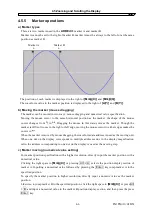
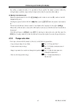
Page 35: ...e cursor to either edges makes the cursor to When the marker is moved by mouse dragging the waveform data address is used as the moving unit When one dot on the display corresponds to multiple addresses due to the display magnification ratio the address corresponding to one dot on the display is used as the moving step c Marker moving numerical value setting For marker position specification with ...

Page 36: ...e right of dX When either of the markers is moved the other marker is also moved with the distance between them being kept Click the right space to dX or press Alt and input a numerical value and then press the Enter key to jump marker B so that the distance between the markers becomes the specified value 4 5 6 Range selection The range selected with the marker is effective in the following operat...

Page 37: ...alue display to the right of MrkA X or MrkB X For example when the horizontal axis position for marker A is 5 and that for marker B is 10 the selection range will be 5 X 10 Marker A is located just before 5 so 5 is between marker A and marker B Marker B is located just before 10 so 10 is not between marker A and marker B IM FG410 61EN 4 8 ...

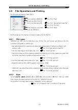
Page 38: ...6 3 Specialized format file Text file containing waveform data only txt See 4 6 4 Text file Specialized format text file containing standard waveform types as well as parameters numerical expression waveform s constants and expressions wfn See 5 1 5 File operation Text file containing control points only prn See 5 3 3 File operation Original format text file of PWF parameter information PWF See 5 ...

Page 39: ...ting File Save As WDB Alt F A or Ctrl A displays the screen titled Save As Select a saving location input a file name and click the Save button The file extension is wdb and can be omitted during file name input Saving location Input file name 4 6 4 Text file Waveform data created using the ARB Edit can also be saved in a text file so that other applications can easily handle it Selecting File Sav...

Page 40: ... ARB Edit can read the text file created using the text editor When creating an integer number format text file put one data unit which must be a 16 bit signed integer 32768 to 32767 on one row The number of data units in a data file should be 524288 or smaller If the number of data units in a data file is larger than 524288 cannot be read If the number of data units is smaller than the system set...

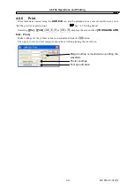
Page 41: ...out See 4 3 Setting Menu Selecting File Print Alt F P or Ctrl P displays the screen titled YOKOGAWA ARB Edit Print Make settings for the printer or font as needed and click the OK button The upper lower and left margins cannot be set when printing the waveform Margin setting is invalid when printing the waveform Printer settings Font specification IM FG410 61EN 4 12 ...

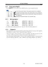
Page 42: ...r Ctrl V Delete Edit Delete Alt E D or Ctrl D For details on each editing operation see Figure 4 2 Waveform Editing Operation 4 7 2 Clipboard Executing the cut or copy operation sends the waveform data in the selected range to the clipboard The clipboard is a temporary data storage area provided in Windows The waveform data in the selected range is sent to the clipboard The data equivalent to 16 b...

Page 43: ...ame Clipboard Selected range Paste When the clipboard data is smaller 0 is embedded at the end Paste When the clipboard data is larger The overflowed section disappears Delete Though the selected part is deleted the clipboard remains unchanged Figure 4 2 Waveform Editing Operation IM FG410 61EN 4 14 ...

Page 44: ...4 7 Copy and Paste IM FG410 61EN 4 15 ...

Page 45: ......

Page 46: ... 3 1 Control point setting 5 14 5 3 2 Interpolation 5 14 5 3 3 File operation 5 15 5 4 Operation Between Waveforms 5 16 5 4 1 Operation types 5 16 5 4 2 Object of operation 5 16 5 4 3 Operation execution 5 17 5 5 PWF Parameter Variable Waveform 5 18 5 5 1 Waveform selection 5 19 5 5 2 Parameter setting 5 19 5 5 3 PWF parameters 5 19 5 5 4 File operation 5 20 5 5 5 Print 5 21 5 6 Transferring the W...

Page 47: ...rm and Numerical Expression Waveform The waveform generation screen is used to generate the standard waveform and numerical expression waveform Click the button on the toolbar or select Tool Wave Create Alt T C to open the waveform generation screen Immediately after returning to the waveform display screen after creating a waveform on the waveform generation screen the status before waveform crea...

Page 48: ...e Directly input a number in the numerical value input area between the buttons and press the Enter key to jump to the specified page The page numbers range from 1 to 200 To return the settings on the displayed page to the default values select Edit Page Clear Alt E P on the waveform generation screen To return all pages to the default values at once select Edit All Page Clear Alt E A on the wavef...

Page 49: ...ve the duty ratio and transition can be set The duty ratio unit is The transition sets the time for the wave height value to go between 0 and 100 with the ratio to the cycle If the DC Offset or Amplitude setting exceeds the full scale value the waveform is clipped at the full scale value When the mouse cursor is moved to the waveform display area on the waveform generation screen the shape of mous...

Page 50: ... at the bottom of the screen To create the waveform on the displayed page only click the Page OK button at the bottom of the screen To return to the waveform display screen without creating a waveform click the Cancel button at the bottom of the screen or press the Esc key a Constants Describe the constant in the constant value or expression format such as fs 32767 and s 2 pi 4096 Be sure to suffi...

Page 51: ...ncluded into ARB Edit at factory If the constant defined in a constant has the same name as the built in constant the defined value or expression takes effect Table 5 2 Built in Constants Name Meaning Value pi Circle ratio 3 1415926535898 c Light speed 2 99792458e8 h Planck constant 6 6260755e 34 k Boltzmann constant 1 380658e 23 r Euler constant 0 57721566490153 c Functions Specify a numerical ex...

Page 52: ...esult of this expression is a waveform with a very small amplitude close to 0 When the vertical axis unit is Voltage and the amplitude is 20 Vp p the range is 10 so the result of this expression is 1 10 of a full scale sine wave When the vertical axis unit is User Unit and the range is between 1 and 1 the result of this expression is a full scale sine wave If the calculation results exceed the ful...

Page 53: ...ion_2 2 Triangular wave Expression 1 Phase radian Expression 2 Slope 0 100 sqw expression_1 expression_2 expression_3 3 Square wave Expression 1 Phase radian Expression 2 Duty ratio 0 100 Expression 3 Displacement 0 100 rnd 0 Noise waveform f Inter waveform numerical expression examples Some sample inter waveform numerical expressions are shown below In an example where there is only one page the ...

Page 54: ...ant a 19 5 Y sin a x sin b x 2 b 20 5 CR charge discharge waveform horizontal axis user unit 0 to 1 vertical axis user unit 1 to 1 Page 1 Area X 0 to 0 5 Constant j 15 Y 1 2 exp x j Page 2 Area X 0 5 to 1 Constant j 15 Y 1 2 exp x 0 5 j Differentiation waveform horizontal axis user unit 0 to 1 vertical axis user unit 1 to 1 Page 1 Area X 0 to 0 5 Constant j 15 Y exp x j Page 2 Area X 0 5 to 1 Cons...

Page 55: ...ining the waveform generation screen settings select File Open Alt F O or Ctrl O When the screen titled Open appears select a file location input a file name and click the Open button Because the file containing the waveform generation screen settings is a text file the file can be edited using a text editor or other application though this operation is not recommended As a result of editing the f...

Page 56: ... U or pressing Ctrl U 4 4 Undo and Redo 5 2 1 Contraction Extension of horizontal axis Select the range with the markers on the waveform display screen before contracting extending the horizontal axis 4 5 6 Range selection The contraction extension of the horizontal axis is set in the X area on the contraction extension screen a Using the selected range as the compression decompression start end p...

Page 57: ...yed to the right of Min Input the maximum minimum values of the target after contraction extension in each display section and press the Enter key to change the waveform on the waveform display screen If the waveform is hidden behind the contraction extension screen and difficult to see move the screen The waveform can be vertically inverted by setting a value smaller than the minimum value to the...

Page 58: ... results in extension that exceeds the full scale range waveforms are clipped at the full scale range Note that the waveform may be distorted when the rate is too high 5 3 Waveform Generation Through Interpolation The interpolation editing screen is used to create waveforms with different types of interpolation The point set for interpolation is called the control point Click the button on the too...

Page 59: ...e control point with mouse The control point can be moved by dragging the mark on the waveform display screen If the screen magnification ratio is low it might be difficult to capture the mark due to the display resolution When a control point is moved with the mouse linear interpolation is performed and the waveform display area is overwritten d Deleting the control point Click the Delete button ...

Page 60: ...g a waveform on the interpolation editing screen and returning to the waveform display screen the status before waveform creation can be recovered by selecting Edit Undo Alt E U or pressing Ctrl U 5 3 3 File operation The settings on the interpolation editing screen can be saved in a text file Select File Save Alt F S or Ctrl S on the interpolation editing screen The screen titled Save As appears ...

Page 61: ...operations are in the selected range Select the range beforehand on the waveform display screen with markers A and B 5 4 1 Operation types Clicking the button to the right of the arithmetical operations list is displayed Select an operator by clicking the item in the list or pressing the keys Note that indicates multiplication and indicates division 5 4 2 Object of operation a Waveform generation ...

Page 62: ...Operation execution Clicking the button displays the result of inter waveform operation in Operation Result Click the OK button to return to the waveform display screen and reflect the operation result Click the Cancel button or press the Esc key to return to the waveform display screen without performing any operation It is recommended to set the vertical axis unit to the custom unit 1 to 1 espec...

Page 63: ... or by pressing Ctrl U Figure 5 6 PWF Screen For details on PWF waveforms refer to FG410 FG420 Application Instruction Manual The waveform data that can be generated from the PWF screen includes single polarity waveforms On the ARB Edit PWF screen waveform data can be generated in the full scale range even for such waveforms Change the settings of the amplitude range of the oscillator as necessary...

Page 64: ...t the desired parameter and move Slider in Parameter Setting to update the displayed waveform Moreover the parameter setting value is also changed 5 5 3 PWF parameters The 25 types of waveforms that can be used on the PWF screen their parameters and their setting ranges and resolutions are listed below Table 5 5 Steady Sine Group Waveform Parameter Minimum Value Maximum Value Resolution Unbalanced...

Page 65: ...se Surge Tr 0 01 100 00 0 01 Td 0 01 100 00 0 01 Table 5 10 Others Group Waveform Parameter Minimum Value Maximum Value Resolution Trapezoid with Offset Delay 0 00 100 00 0 01 Rise 0 00 100 00 0 01 UpperBase 0 00 100 00 0 01 Fall 0 00 100 00 0 01 Offset 0 00 100 00 0 01 Half Sine Edge Pulse LE 0 00 100 00 0 01 TE 0 00 100 00 0 01 Duty 0 00 100 00 0 01 Bottom Referenced Ramp Symm 0 00 100 00 0 01 5...

Page 66: ... normally read Other files that ARB Edit can handle 4 6 1 File types 5 5 5 Print The setting conditions for the PWF screen can be also printed out Selecting File Print Alt F P or Ctrl P displays the screen titled YOKOGAWA ARB Edit Print Make settings for the upper lower and left margins the printer or font as needed and click the OK button IM FG410 61EN 5 21 ...

Page 67: ...stem Setup Screen System Setup The system setting screen consists of four tab pages System Unit Waveform and Oscillator 5 6 1 Model setting The Basic Setup frame on the System page is used select the signal generator model and the interface and set the serial number a Selecting the target model Click the button to the right of Model to display the list of supported signal generator models Click on...

Page 68: ...n None can be selected Check the signal generator to be connected for its serial number 5 6 2 Axis unit setting Figure 5 8 System Setup Screen Unit Setup In the X Axis Unit and Y Axis Unit fields on the Unit page perform the settings of the horizontal axis and vertical axis for waveform display On the system setting screen double click the Unit Setup to enable the Unit page a Horizontal axis unit ...

Page 69: ...le 1 to 1 Use this to align with the vertical axis range when the custom unit for the vertical axis is 1 0 to 360 degrees 0 to 400 grads 0 to 6 283185 radians b Vertical axis unit The voltage and the custom unit can be used as the display setting unit of vertical axis in addition to the waveform data 16 bits 32768 to 32767 The voltage is interlocked with Amplitude and DC Offset in Oscillator For e...

Page 70: ...n be set with up to 20 one byte alphanumerical characters One byte katakana and double quotation marks cannot be used b Waveform memory number Click the button to the right of Memory Number to select a waveform memory number Click to increase the memory number and click to decrease the memory number It is also possible to directly input a numerical value in the numerical value display area FG410 F...

Page 71: ...ion editing screen The array format consists of data strings corresponding to waveform memory addresses The data of the control point format described previously is created from data in this array format d Waveform memory size If Array Format is selected as the transfer format Memory Size becomes selectable In the case of Control Point Format manipulation is not possible Click the button to the ri...

Page 72: ...off frequency cycle output range amplitude DC offset and amplitude range Click the Unit tab on the system setting screen the Unit page is enabled The relationship between the signal generator models and settable items is shown in Table 5 12 Signal Generator Setting Table 5 12 Signal Generator Setting FG410 FG420 Channel Output on off Frequency Period Output range Amplitude DC offset Amplitude rang...

Page 73: ... numerical value in this status and press the Enter key to determine the value Changing the cycle setting also updates the frequency display e Range Click the button to the right of Range to display the list of selectable output ranges Click one in the list or press the keys to select an output range In the FG420 and FG420 the setting is fixed to Auto f Amplitude Click the input area to the right ...

Page 74: ...ers among the oscillator settings observe the following cautions Data cannot be transferred unless the driver software is installed normally 2 2 1 Installing the USB driver software Do not perform any operation using the ARB Edit during data transfer Even when multiple ARB Edits are running it is not possible to transfer data from multiple ARB Edits at the same time 5 6 6 File operations The setti...

Page 75: ... on the system screen and initialized when the ARB Edit is started are shown in Table 5 13 Initialized Values Table 5 13 Initialized Values FG410 FG420 Waveform memory name No specification Waveform memory number 0 Channel 1 Output on off OFF Frequency Hz 1000 Period sec 1m Output range Auto Amplitude Vp p 0 1 DC offset V 0 0 Amplitude range Norm FS X axis unit Custom X axis name No specification ...

Page 76: ...6 ERROR MESSAGES 6 1 Arbitrary Wave Edit Software Error 6 2 IM FG410 61EN 6 1 ...

Page 77: ...eform operation executed for the clipboard If this error persists restart the ARB Edit Clip Board Read error Clip Board Write error Clip Board error Constant format error An arbitrary function expression for waveform generation contains an error Modify the error cause according to the message Syntax error in equation Lack of parenthesis Unbalance of parenthesis Divided by 0 Compile error The unit ...

Page 78: ...7 MAINTENANCE 7 1 Handling CD ROM 7 2 7 2 Replacement of Damaged CD ROM 7 2 7 3 Version Check 7 2 IM FG410 61EN 7 1 ...

Page 79: ...ertical or horizontal position so that it would not be deformed When writing on the label surface of the CD ROM use a felt tipped pen Do not use anything with a hard point such as a ball point pen or pencil 7 2 Replacement of Damaged CD ROM If the Arbitrary Wave Edit Software CD ROM is damaged contact Yokogawa Test Measurement Corporation or your local distributor We will replace it with a new CD ...

Page 80: ......

Page 81: ... of the information contained in this user s manual please notify Yokogawa Test Measurement Corporation or an Yokogawa Test Measurement Corporation sales representative in case any unclear points errors or omissions are found 4 Yokogawa Test Measurement Corporation shall not be held responsible for any errors defects lost profits or other consequential damages arising from the use of this product ...

Page 82: ......

Page 83: ...https www yokogawa com ymi Yokogawa Test Measurement Corporation ...

Reviews: