6-19
IM 04L57B01-01JA
GX/GP/GM Communication Commands
1
2
3
4
5
6
App
6.7 Format of the Data Block of Binary Output
6.7.1
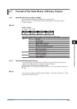
Most Recent Channel Data (FData)
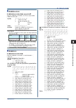
Wireless input unit data dropout is added to the alarm (32 bits).
See section 2.11.1, “Most Recent Channel Data (FData)” in the Communication
Command Manual.
Block 1
Alarm (32 bits)
Indicates the alarm status.
Alarm 1
Alarm 2
Alarm 3
Alarm 4
8 bits
8 bits
8 bits
8 bits
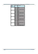
The eight bit values of alarm 1 to alarm 4 are described in the table below.
Bit
Value
Description
0 to 5
0
No alarm
1
High limit alarm
2
Low limit alarm
3
Difference high limit alarm
4
Difference low limit alarm
5
High limit on rate-of-change alarm
6
Low limit on rate-of-change alarm
7
Delay high limit alarm
8
Delay low limit alarm
9
Wireless input unit data dropout alarm
6
0
No alarm is activated.
1
An alarm is activated.
7
0
Alarm nonhold state
1
Alarm hold state
6.7.2
Channel FIFO Data (FFifoCur)
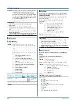
The output in response to the command "FFifoCur,0" is shown below. Outputs the I/O
channel, math channel, and communication channel FIFO data.
Wireless input unit data dropout is added to alarms.
See section 2.11.2, “Channel FIFO Data (FFifoCur)” in the Communication Command
Manual.
Block
The content of the block is the same as that of “Block 1” described in section 6.7.1, “Most
Recent Channel Data (FData).”
Summary of Contents for GX70SM
Page 1: ...User s Manual IM 04L57B01 01EN 1st Edition Model GX70SM Wireless Input Unit User s Manual ...
Page 2: ......
Page 12: ...Blank ...
Page 148: ...Blank ...
Page 168: ...Blank ...

