1-14
IM 04L57B01-01EN
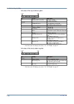
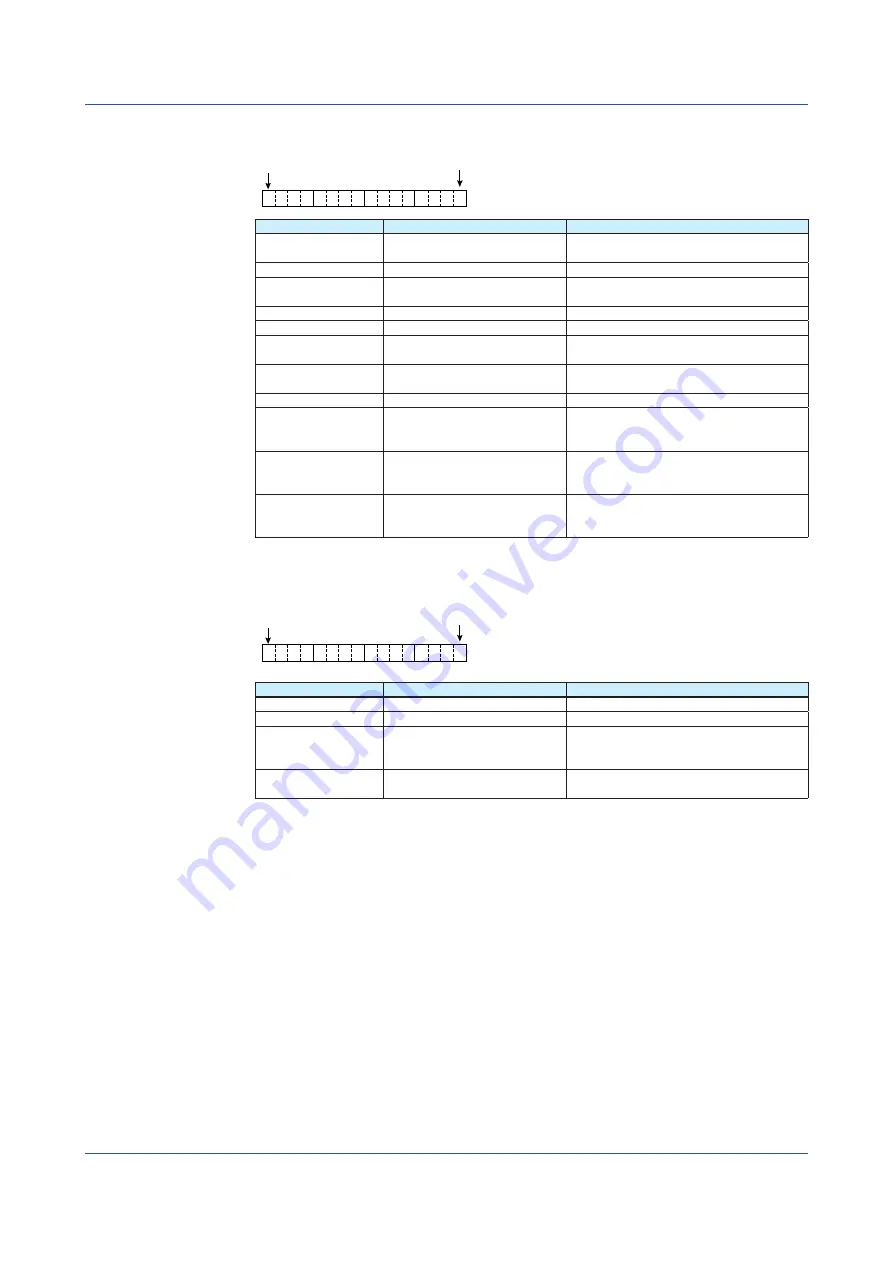
Structure of the input status register
bit 15
bit 0
bit
Content
Description
15
Humidity option availability
1: Option available
0: Option not available
14 to 10
—
9
Configuration error
1: Configuration not complete
(LED display: Mode setting error)
8
—
7
Critical Low Battery
1: Battery flat
6
Low Battery
1: Low battery
(LED display: Low battery warning)
5
OVER
1: Detection of input outside the measurable
range
4
Burnout
1: Burnout detection
3
Calibration value error
1: Detection of an error in the calibration
value
(LED display: Input error)
2, 1
Hardware error
A value other than 00: Detection of a
hardware error
(LED display: Input error)
0
Memory error
1: Detection of an error in the setting
information or logging data
(LED display: Mode setting error)
* For details on the LED display, see section 1.2.6, “LED Display” on page 1-6.
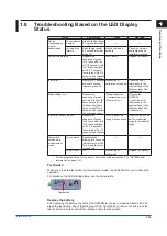
Structure of the device status register
bit 15
bit 0
bit
Content
Description
15 to 3
—
—
2
USB connection
1: USB connection present
1
Mode setting error
1: Mismatch between the current status and
the operation mode at startup
(LED display: Mode setting error)
0
Input error
1: Input error detection
(LED display: Input error)
* For details on the LED display, see section 1.2.6, “LED Display” on page 1-6.
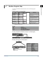
1.7 Modbus Register Map
Summary of Contents for GX70SM
Page 1: ...User s Manual IM 04L57B01 01EN 1st Edition Model GX70SM Wireless Input Unit User s Manual ...
Page 2: ......
Page 12: ...Blank ...
Page 148: ...Blank ...
Page 168: ...Blank ...


