2-41
IM 04L57B01-01EN
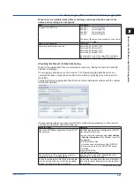
How to Use the W
ireless Input Unit Configurator
1
2
3
4
5
6
App
RJC of TC Input
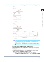
As the measurement terminal of the GX70SM is generally at room temperature, the actual
output of the thermocouple is different from the values given on the thermoelectromotive
force table based on 0°C. The GX70SM performs compensation by measuring the
temperature at the input terminal and adding the corresponding thermoelectromotive force to
the actual output of the thermocouple. Therefore, when the measurement terminal is shorted
(equivalent to the case when the detector tip is 0°C), the measured value indicates the
temperature of the input terminal.
When calibrating the GX70SM, this compensation voltage (thermoelectromotive force of
0°C reference corresponding to the input terminal temperature) must be subtracted from the
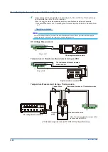
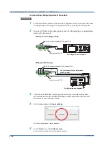
output of the standard generator before application. As shown in the figure, by using the 0°C
standard temperature device to compensate the reference junction at 0°C, you can input the
thermoelectromotive force of 0°C reference from the DC voltage standard and perform the
calibration.
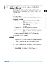
Built-in Humidity Sensor Calibration Procedure
Procedure
1
Warm up the reference device sufficiently.
2
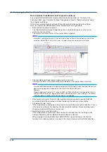
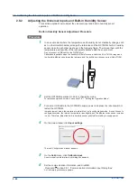
In an environment where the temperature and humidity do not drastically change, such
as in a thermostat chamber, arrange the reference and the GX70SM’s built-in humidity
sensor close to each other as shown in the following figure.
3
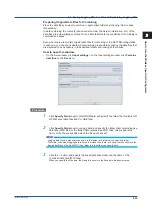
Determine the error from the difference between the humidity value of the reference
and that of the GX70SM.
When the error is outside the measuring accuracy specifications, adjustment is pos-
sible.
Procedure: section 2.8.2, “Adjusting the Universal Inputs and Built-in Humidity Sen-
2.8 Calibrating the Universal Inputs and Built-in Humidity Sensor
Summary of Contents for GX70SM
Page 1: ...User s Manual IM 04L57B01 01EN 1st Edition Model GX70SM Wireless Input Unit User s Manual ...
Page 2: ......
Page 12: ...Blank ...
Page 148: ...Blank ...
Page 168: ...Blank ...


