background image

3-2

IM 04L57B01-01EN

3.2  Configuring to Automatically Connect Wireless 

Input Units to the GX/GP/GM (Coordinator)

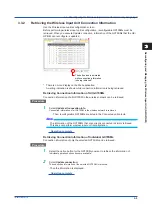
3.2.1 

GX/GP/GM Coordinator Configuration

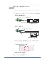
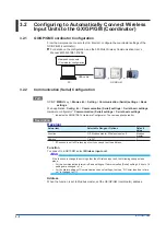
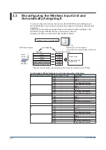
From the maintenance console (by Oki Electric), configure the coordinator settings of the 

GX/GP/GM (coordinator).

  For details on the configuration, see the 920 MHz Wireless Communication User’s 

Manual (IM 04L51B01-41EN).


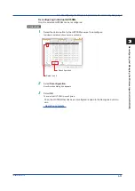
USB cable

GX/GP/GM

Maintenance console

• Coordinator configuration

PC

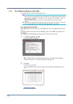
3.2.2 

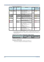
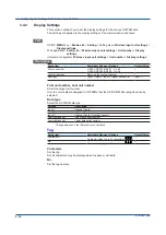
Communication (Serial) Configuration

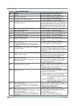
Path

GX/GP:  

MENU

 key > 

Browse

 tab > 

Setting

 > 

Communication (Serial) settings

 > 

Basic 

settings

Web application:  

Config.

 tab > 

Communication (Serial) settings

 > 

Serial basic settings

Hardware configurator*: 

Communication (Serial) settings

 > 

Serial basic settings

*  Indicates the S Hardware Configurator. The same applies hereafter.

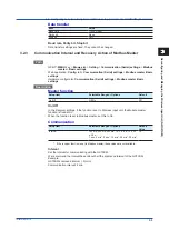
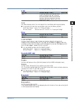
Description

Receiver

Setup Item

Selectable Range or Options

Default 

Value

Function

Off, Modbus master, Wireless input unit

Modbus 

master

Address*

1 to 247

1

*  If Function is set to Wireless input unit, you cannot set the address.

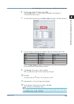
Function

To connect to a GX70SM, select 

Wireless input unit

.

Note

If the function is change to anything other than Wireless input unit, the following changes take 

place.

•  For the communication interval in Basic settings of Communication (Serial) settings, 5 min to 1 h 

settings are changed to 1 s.

•  For the Alarm settings of Communication channel settings, the type “D: Comm lose due to time 

out” is changed to Off.

Address

When the function is set to Modbus master, set the GX/GP/GM (coordinator) address.

Summary of Contents for GX70SM

Page 1: ...User s Manual IM 04L57B01 01EN 1st Edition Model GX70SM Wireless Input Unit User s Manual ...

Page 2: ......

Page 3: ... User s Manual IM 04L51B01 17EN For details on the 920 MHz wireless communication of the GX GP GM see the following manual Model Manual Title Manual No Common to GX GP GM 920 MHz Wireless Communication CM2 and CS2 User s Manual IM 04L51B01 41EN To ensure correct use please read this manual thoroughly before beginning operation The following manuals are provided for the GX70SM Paper Manuals Manual ...

Page 4: ...ctly prohibited Trademarks SMARTDAC and SMARTDACPLUS are registered trademarks of Yokogawa Electric Corporation Microsoft and Windows are registered trademarks or trademarks of Microsoft Corporation in the United States and other countries Pentium is a trademark of Intel Corporation in the United States and or other countries Adobe and Acrobat are registered trademarks or trademarks of Adobe Syste...

Page 5: ...he procedure to check the version see the following sections 2 9 2 Wireless Communication Module Firmware on page 2 47 2 9 3 Input Module Firmware on page 2 48 Edition Product Addition and Change Remarks Module Version 1 Wireless communication module vc1 0 1 Input module R1 01 01 GX GP GM Main Unit Version Supporting the Wireless Input Unit GX GP GMs with release number 4 02 and later support the ...

Page 6: ...e the respective manuals The following terms are used for references to other manuals Notation Description GX GP User s Manual Model GX10 GX20 GP10 GP20 Paperless Recorder User s Manual Refers to the IM 04L51B01 01EN GX GP First Step Guide Model GX10 GX20 GP10 GP20 Paperless Recorder First Step Guide Refers to the IM 04L51B01 02EN GM User s Manual GM Data Acquisition System User s Manual Refers to...

Page 7: ...ator It explains the auto assignment of the GX70SM and the channel assignment and management of received data and so on that take place when the wireless input unit is reconfigured 4 Functions Added with Wireless Input Unit Support GX GP GM Hardware Configurator This chapter describes the functions that are added with the GX70SM support of the GX GP GM 5 Displaying Logging Data and Combined Data U...

Page 8: ...ntion to actions or conditions that could cause light injury to the user or cause damage to the instrument or user s data and precautions that can be taken to prevent such occurrences Note Calls attention to information that is important for the proper operation of the instrument Reference Item Reference to related operation or explanation is indicated after this mark Example section 4 1 Conventio...

Page 9: ... Input Unit 1 12 1 7 Modbus Register Map 1 13 1 8 Troubleshooting Based on the LED Display Status 1 15 1 9 Replacing Devices 1 16 Chapter 2 How to Use the Wireless Input Unit Configurator 2 1 Overview of the Wireless Input Unit Configurator 2 1 2 1 1 Configuration Function of the Wireless Input Unit Configurator 2 1 2 2 Installation 2 2 2 2 1 System Requirements 2 2 2 2 2 Installing the Wireless I...

Page 10: ... Input Unit Reconfiguration Screen 3 5 3 3 2 Retrieving the Wireless Input Unit Connection Information 3 9 3 3 3 Reconfiguring Wireless Input Units 3 10 3 4 Configuring the Settings for Wireless Input Unit Data 3 12 3 4 1 Enabling Channels and Setting the Span Decimal Point Unit and the Like 3 12 3 4 2 Alarm Settings 3 14 3 4 3 Display Settings 3 16 3 4 4 Setting Calibration Correction Linearizer ...

Page 11: ... Unit Functions of the Universal Viewer R3 05 and later 5 1 5 1 1 Files That Can Be Displayed and Their Extensions 5 1 5 1 2 Waveform Display of Logging Data 5 2 5 1 3 Waveform Display of Combined Data 5 3 5 1 4 Alarm List Display 5 4 5 1 5 Signing Data Files 5 4 5 1 6 Listing the Operation Log 5 4 Chapter 6 GX GP GM Communication Commands 6 1 Added and Changed Commands 6 1 6 1 1 Added and Change ...

Page 12: ...Blank ...

Page 13: ... authentication function blocks unauthorized access In addition communication encryption prevents tampering and wiretapping The battery life is 5 years when the scan interval is set to 5 minutes standard operating conditions 1 standard mode Power can also be supplied through the USB port 2 1 For the standard operating conditions see the GX70SM Wireless Input Unit General Specifications GS 04L57B01...

Page 14: ...reason a logging data file can be used to interpolate the data during which acquisition failed Note There are certain GX GP GM settings that need to be configured to combine data See section 2 7 Saving Logging Data to a File and Combining Logging Data For details on setting the type of data to record see the following manuals GX GP User s Manual 1 12 1 Setting the Type of Data to Record Display or...

Page 15: ...SM operation mode switch See section 1 5 Setting the Operation Mode of Wireless Input Units on page 1 11 Measurement Configuration maintenance Measurement mode Configuration mode Operation mode switch 1 2 2 Measurement With two universal input channels the GX70SM can measure temperature thermocouple RTD sensor input DC voltage DC current using a shunt resistor and digital input contact voltage In ...

Page 16: ...mV to 200 00 mV 2V 2 0000 V to 2 0000 V 6V 6 000 V to 6 000 V 10V 10 000 V to 10 000 V GS 0 4 2V 0 4000 V to 2 0000 V 1 5V 0 800 V to 5 200 V DI LVL On 1 Off 0 voltage On 2 5 V or more Off 2 3 V or less DI On 1 Off 0 contact Humidity 0 0 to 90 0 RH 1 2 3 Measurement Mode There are two measurement modes Standard mode Power frequency noise riding on the measured signal is rejected Select the power f...

Page 17: ... a certain period Logging data can be retrieved using the Wireless Input Unit Configurator and saved as a file in the PC Wireless transmission Measured data 1 2 3 4500 4 5 Logging data 6 Scan interval Deleted Older Newer New data Old data How new data is saved 1 2 5 Low Battery Warning When the GX70SM battery voltage becomes low a low battery warning is indicated with an LED The GX GP GM can monit...

Page 18: ...r 2 seconds and repeats the entire sequence Joined the network Joining the network Green blinking 1 second intervals When network join authentication is successful Green blinks 5 times 0 5 second intervals and turns off When network join authentication fails Red blinks 5 times 0 5 second intervals and turns off Input error over burnout Repeats the sequence of green lit 0 1 seconds red lit 0 1 seco...

Page 19: ...transmission Serial numbers assigned to data entries sampled by the GX70SM Timeout Read cycle Data serial number 101 102 103 104 104 104 No change in data serial number Alarm output Data dropout detection 1 2 10 Device Information Output for Wireless Input Unit Errors GX GP When a battery error operation error communication disconnection or the like occurs on the GX70SM device information can be o...

Page 20: ...0SM input settings using the Wireless Input Unit Configurator See section 2 6 Configuring the Input Settings of the Wireless Input Unit 8 Switch the GX70SM operation mode to measurement mode See section 1 5 1 Setting the Operation Mode 9 Perform coordinator configuration on the GX GP GM coordinator using the maintenance console by Oki Electric For details on the coordinator configuration of the GX...

Page 21: ...ent of the GX70SM Environment configuration COM port Password 1 2 4 5 6 10 11 9 Wireless input unit settings Span Alarm Indicator Comm time out Auto message 12 PC PC GX70SM GX GP GM GX70SM operation mode change switch to configuration mode 3 7 GX70SM operation mode change switch to measurement mode Wireless input unit settings Maintenance console Wireless input unit configuration Maintenance conso...

Page 22: ... the Modbus master settings in the Communication Serial settings of the GX GP GM coordinator specify the command settings Note For the communication channel do not use the communication channel as signed to the GX70SM 3 Configure the GX GP GM communication channel settings 4 Configure the GX GP GM display group settings recording channel settings and other settings necessary for data collection ac...

Page 23: ...figuration When switching to configuration mode supply power through USB If you change to the configuration mode without supplying power through the USB measurement starts in measurement mode after you press the reboot switch Reboot switch Operation mode switch Supply power through USB when changed to configuration mode O N 1 2 ON OFF Operation mode SW1 Measurement mode OFF Configuration mode ON W...

Page 24: ...t The internal antenna of the GX70SM has directivity As shown in the following figure the field intensity in the 0 and 180 directions is weak so the installation direction needs to be considered carefully Avoid facing the coordinators and routers toward the 0 or 180 direction 0 90 270 180 ...

Page 25: ...vice status 40018 UINT16 RSSI value dBm 40019 INT16 Received signal strength on the coordinator repeater Elapsed time s 40020 UINT16 Elapsed time on the coordinator An approximate reference value Data type Symbol Description INT16 16 bit signed integer UINT16 16 bit unsigned integer UINT32_L 32 bit unsigned integer little endian FLOAT_L 32 bit floating point little endian Structure of the Data Ser...

Page 26: ...value LED display Input error 2 1 Hardware error A value other than 00 Detection of a hardware error LED display Input error 0 Memory error 1 Detection of an error in the setting information or logging data LED display Mode setting error For details on the LED display see section 1 2 6 LED Display on page 1 6 Structure of the device status register bit 15 bit 0 bit Content Description 15 to 3 2 US...

Page 27: ...equence Mode mismatch Configuration error Memory error Restart the GX70SM Check the error information in the input settings of the Wireless Input Unit Configurator Input error over burnout Repeats the sequence of green lit 0 1 seconds red lit 0 1 seconds and all off 1 8 seconds twice turns off for 10 seconds and repeats the entire sequence Out of measuring range disconnection Check the input and s...

Page 28: ... minutes If you want B to immediately join the network press the GX GP GM wireless communication module s reboot switch or restart the GX GP GM note that in this case the network is reconfigured Device replacement illustration A C B E 1 0001 3 0003 5 0005 A Station number short address Replace C E GX GP GM coordinator GX70SM 1 0001 1 In this example short address A is replaced with B with the same...

Page 29: ... of the GX70SM Environment Configuration You can set the operating environment of the Wireless Input Unit Configurator including the USB COM port for connecting the GX70SM to the PC the GX70SM password and the default folder for saving setup data Calibrating and Adjusting the Universal Inputs and Built in Humidity Sensor You can calibrate and adjust the universal inputs and built in humidity senso...

Page 30: ...on Pro 32 bit edition or 64 bit edition Other Operating Conditions Microsoft NET Framework 4 6 1 or later is required to connect to the GX70SM and run the application Visual C 2010 Redistributable Package x86 is required To view the user s manual of this software you need to use Adobe Reader 7 or later by Adobe Systems the latest version recommended Microsoft Internet Explorer 11 is required to do...

Page 31: ... Install 7 When the installation is complete click Finish SMARTDAC STANDARD Wireless Input Unit Configurator will be registered under All Pro grams in the Windows Start menu Operation complete Note Before installing the software check that your PC is not infected by a virus Close all other software applications before installing this software To reinstall the software uninstall the current softwar...

Page 32: ...nection PC USB cable GX70SM If you connect using the USB cable for the first time device driver installation will start Regardless of whether the device driver installation is successful proceed to step 3 and com plete the installation of the USB driver 3 Start Windows Device Manager The procedure to start Device Manager varies depending on the OS that you are using For details see the PC user s m...

Page 33: ...1 2 3 4 5 6 App 5 Click Browse my computer for driver software 6 Click Browse select the USB_Driver folder in the installation folder of the Wireless Input Unit Configurator and click OK 7 Click Install 8 When the installation is complete click 2 3 Connection and Startup ...

Page 34: ...70SM communicates with Operation complete Note Power supply from USB is required to configure the GX70SM Use a powered USB cable Do not disconnect the USB cable or turn off the power when the Wireless Input Unit Configurator is connected to the GX70SM If you perform these acts while data is being written to the GX70SM during firmware updating or configuration the configuration information may beco...

Page 35: ...x appears when you start the software for the first time after installation select Allow access The Wireless Input Unit Configurator starts and the main window appears Operation complete Note If a Microsoft NET Framework warning appears the first time you start the Wireless Input Unit Configurator install Microsoft NET Framework 4 6 1 or later For details on installing Microsoft NET Framework visi...

Page 36: ...ain window Wireless settings button This button opens a wireless setting window of the GX70SM Procedure section 2 5 Configuring the Wireless Settings of the Wireless Input Unit Input settings button This button opens an input setting window of the GX70SM Procedure section 2 6 Configuring the Input Settings of the Wireless Input Unit Device settings button This button opens a window for setting the...

Page 37: ...d you entered in New password again for confirmation Set Click Set to set the entered password in the GX70SM From this point enter this password when connecting to the GX70SM To apply the settings to the GX70SM press the reboot switch to restart the GX70SM The default password is default Omit password Omit password If you select this option you can omit entering the password for connecting to the ...

Page 38: ...d to the specified folder Set Click Set to save the File path setting in the Wireless Input Unit Configurator Note If you forget the password for connecting to the GX70SM from the Wireless Input Unit Configurator you cannot reset the password from the Wireless Input Unit Configurator If you forget the password servicing will be required Contact your nearest YOKOGAWA dealer 2 4 Environment Configur...

Page 39: ... settings button Menu Bar The Wireless settings window has the following menus Item Description Menu Exit Closes the Wireless settings window and returns to the main window Tool Firmware update Updates the firmware of the GX70SM wireless communication module Restore factory preset Restores the GX70SM settings to their factory defaults Environment setup Shows the Environment Configurator window Hel...

Page 40: ...rator starts Save preset settings Click Save preset settings to save the values shown for each setup item as preset values used when the Wireless Input Unit Configurator starts Open Setting File Click Open Setting File to show for each setup item the values from the setup file To open a configuration file without an extension csv set the file type to All files Save Setting File Click Save Setting ...

Page 41: ...r Enter the preferred PAN ID 0000 to FFFE to connect to To not specify the preferred PAN ID enter 0000 Radio channel number Select the channel number 1ch to 28 ch Up to 10 channels can be selected Short address Enter a different short address 0001 to FFFD for each GX70SM Select a short address that does not overlap with the short addresses of other devices For the GX70SMs do not set the address to...

Page 42: ... 2 s 5 s 10 s 20 s 30 s 1 min 2 min 5 min 10 min 20 min 30 min 60 min This setting also applies to the input scan interval and logging data interval Status LED Indication Select whether to indicate the GX70SM status using the status LEDs For details on the status LED see section 1 2 6 LED Display on page 1 6 2 5 Configuring the Wireless Settings of the Wireless Input Unit ...

Page 43: ...ith the values in the Input Configuration window Save as Input setting file Saves the values in the Input Configuration window to the PC in a new input setup file WPN file with the specified name Read save the logging data Retrieves logging data from the GX70SM and saves it as a logging data file WLD file Combine data files Inserts a logging data file WLD file into a GX GP GM event data and saves ...

Page 44: ...er s manual this manual Version Shows the version information of Input settings program Web to update Shows the firmware update website Toolbar The toolbar in the Wireless Unit Input Configuration window has the following buttons New Open Input setting file Save overwrite input setting file Read input settings Change input settings About Item Description New Creates new GX70SM input settings Open ...

Page 45: ...ted Depending on the measuring range measurement errors will be large due to the effects of noise and the values may fluctuate The battery life running time on battery is 1 3 to 1 5 times longer than in normal mode Noise rejection Sets the power frequency for rejecting power frequency noise when the operation mode is standard 50Hz 50 Hz noise is rejected 60Hz 60 Hz noise is rejected Temperature un...

Page 46: ...sword box appears enter the password for connecting to the GX70SM from the Wireless Input Unit Configurator Measurement date Shows the PC s date when Execute meas was previously clicked Input 1 Shows the measured value or data status of input 1 Input 2 Shows the measured value or data status of input 2 Input 3 Shows the measured value of the built in humidity sensor RH option or the data status Th...

Page 47: ...on window Comment Set the comment that is entered in the input settings change log when settings are changed This appears only when the information set in the Input Configuration window is applied to the GX70SM File Click the button and specify the save destination folder and the name of the logging data file WLD file The default file name is as follows aaa_bbb WLD aaa Serial number of the connect...

Page 48: ...n area in section 2 6 Configuring the Input Settings of the Wireless Input Unit on page 2 15 3 Configure the universal input and built in humidity sensor Procedure section 2 6 4 Configuring the Universal Input and Built in Humidity Sen sor 4 On the File menu click Save as Input setting file 5 Specify the folder to save the input setup file WPN file to and the file name and click Save The input set...

Page 49: ... Set the operation mode and noise rejection Procedure see the explanation of the configuration area in section 2 6 Configuring the Input Settings of the Wireless Input Unit on page 2 15 5 Configure the universal input and built in humidity sensor Procedure section 2 6 4 Configuring the Universal Input and Built in Humidity Sen sor 6 On the File menu click Save overwrite input setting file The inpu...

Page 50: ...ouple Internal Uses the reference junction compensation function of the GX70SM External Uses an external reference junction compensation function You can set this when the type is set to TC Temperature When the mode is set to external set the compensation temperature Burnout Sets burnout detection Off Does not detect burnouts in the sensor Up When the sensor burns out the measured result is set to...

Page 51: ...Open dialog box appears 3 Select the input setup file WPN file you want to edit and click Open Input settings are displayed 4 On the Read change settings menu click Change input settings A communication information input dialog box appears 5 Set the communication information and click OK Procedure section 2 6 1 Communication Information Input Dialog Box A Change input settings dialog appears 6 Cli...

Page 52: ... the communication information and click OK Procedure section 2 6 1 Communication Information Input Dialog Box A Read input settings dialog appears 4 Click OK The input settings are retrieved When the process is finished a Read input settings dialog box appears 5 Click OK The input settings retrieved from the GX70SM and the wireless input unit information are shown on the Input Configuration windo...

Page 53: ...put settings were applied to the GX70SM Device serial no Shows the GX70SM s serial number Input setting change number Shows the following number aaa_bbb_ccc aaa 8 digit serial number bbb MAC address of the PC used to apply the input settings ccc Name of the PC used to apply the input settings Comment on changing settings Shows the comment that was entered when the input settings were applied Setti...

Page 54: ...within a GX GP GM event data file GEV or GSE file to create a combined data file WLC file Environmental fluctuations and effects from other wireless devices may cause a communication error and data collection dropout Logging data file GX70SM Event data file GX20 GP20 GM10 File combining Combined data file Note There are certain GX GP GM settings that need to be configured in advance to combine dat...

Page 55: ...nstalled channel numbers and display In Universal Viewer these are shown as follows Name on the GX70SM Universal Viewer Channel number Scale Decimal point Unit string Color Input 1 universal input CH0001 According to the range setting in Input settings Red Input 2 universal input CH0002 According to the range setting in Input settings Green Input 3 humidity CH0003 0 0 to 100 0 1 RH Blue Inputs set...

Page 56: ...settings immediately before the logging data was measured Input 1 2 range type Input 1 2 range Input 3 humidity only when the RH option is installed On Off Reboot This indicates that the GX70SM was restarted immediately before the logging data was measured This is assigned only when the unit is restarted as a result of a reboot or the like when there is no change to the scan send interval or range...

Page 57: ...interval 5 minutes restarting twice no range setting change LoggingData WLD Files folder LoggingData_0001 5min WLD LoggingData_0002 5min Reboot WLD LoggingData_0003 5min Reboot WLD Scan send interval change from 5 to 10 minutes LoggingData WLD Files folder LoggingData_0001 5min WLD LoggingData_0002 10min WLD Scan send interval range setting change LoggingData WLD Files folder LoggingData_0001 5min...

Page 58: ...wed using SMARTDAC Universal Viewer This indicates the period from when the alarm D Comm lose due to time out is set to on until it is set to off on the GX GP GM This period is hereafter referred to as the data loss period Explanation of Data Combine The data combine function combines data using the following data file information Determination of the GX GP GM data loss period The data loss period...

Page 59: ...rget unit of Event data Set recording to On Yes Data save settings File format Set to Binary 6 The following setting and operation are not necessary but helps in the operation after combining the data Item Required setting and operation Auto setup Wireless input unit settings On Off Span On Off Span lower upper decimal point unit string Set Span Lower Span Upper Decimal place and Unit of the targe...

Page 60: ...a loss end time Occurrence Release 1 Yes Yes Irrelevant Normal determination Time of alarm occurrence Time of alarm release 2 Yes No Irrelevant Determination when a file is saved with data loss Time of alarm occurrence Last data time 3 No Yes Irrelevant Determination when there is a data loss at the beginning of the data First data time Time of alarm release 4 No No Yes Determination when there is...

Page 61: ...hat Are Changed as a Result of Data Combining Combined data files will have the following changes in comparison with the original GX GP GM data files The indication of File Information Model on the SMARTDAC Universal Viewer will be WIU Configurator If the original GX GP GM data file is of an advanced security function GSE file the signature function cannot be used on the combined data file The sig...

Page 62: ...ata and GX GP GM data are not matched the decimal place in the logging data is adjusted to match that of the GX GP GM data Example If logging data input 1 is set to 2 V range 2 0000 to 2 0000 and the GX communication channel setting is 200 00 to 200 00 logging data 1 9876 will be adjusted to 1 99 according to the number of decimal places 2 digits on the GX side before it is combined Data encryptio...

Page 63: ...the Input settings window click Combine data files on the File menu Procedure 1 Click Specify Folder next to GX GP GM data and specify the folder that contains GX GP GM event data files GEV or GSE files 2 Click Specify Folder next to Logging data and specify the folder that contains logging data files WLD files or the folder that contains aaa WLD Files where aaa is the name of the file you specifi...

Page 64: ... aaa_bbb ccc WLC aaa Specified file name bbb Combination number 0001 and up ccc Original GX GP GM data file name2 1 This excludes the case when the file is not saved because data combining is not successful described later 2 If the name is longer than 20 characters an abbreviation is assigned The following is an example showing how combined data files are saved when Combined is specified for the f...

Page 65: ...s a list of those files This list will contain logging data files that none of their data was combined with the original GX GP GM data files If data combining fails even when GX GP GM is configured appropriately or if the result is not what you assumed check the following Items to Check Remarks Check the GX70SM configuration of the GX GP GM data files GX70SM logging data not configured for GX GP G...

Page 66: ...ed If information not related to data combining is corrupt or tampered with data will be combined or saved but Damage Check will be shown as Damaged You can check using About Document Damage Check of the SMARTDAC Universal Viewer If a warning message Wxxxx error message Exxxx is displayed see Description Corrective Action Ref Section in section 2 11 Messages 2 7 Saving Logging Data to a File and C...

Page 67: ...istance setting range resolution 0 2 to 1999 Ω 0 001 Ω Resistance accuracy of the resistance setting range 0 01 of 2 mΩ or better 0 C standard temperature device ZC 114 ZA 10 by Coper Electronics or equivalent Main specifications Standard temperature stability accuracy 0 05 C Temperature and humidity sensor Must meet the following specifications Rotronic temperature and humidity sensor HC2 series ...

Page 68: ... taking into account the reference junction temperature DC Voltage Measurement Wire to CH1 CH1 DC voltage current standard Hi Lo Temperature or Resistance Measurement Using an RTD CH1 The resistance of three lead wires must be equal b A Digital resistance standard H L G B Wire to CH1 Temperature Measurement Using a Thermocouple CH1 Thermocouple wires or TC extension wires Thermocouple wires Copper...

Page 69: ...ture must be subtracted from the output of the standard generator before application As shown in the figure by using the 0 C standard temperature device to compensate the reference junction at 0 C you can input the thermoelectromotive force of 0 C reference from the DC voltage standard and perform the calibration Built in Humidity Sensor Calibration Procedure Procedure 1 Warm up the reference devi...

Page 70: ...nd the built in humidity sensor is within 7 RH 2 Set the GX70SM operation mode to configuration mode For details on operation mode see section 1 5 1 Setting the Operation Mode 3 Connect a USB cable to the GX70SM to supply power and press the reboot switch to restart the GX70SM In measurement mode the operation is intermittent but in configuration mode it is continuous In configuration mode the int...

Page 71: ...nd the built in humidity sensor RH option beforehand and then click Save 10 Click OK An Information dialog box appears 11 Click OK Operation complete Note If an error occurs in the GX70SM the measured values of each channel after executing may show If the above error is a calibration error restarting the GX70SM pressing the reboot switch after clicking Save may clear the error and cause the measur...

Page 72: ...sistance of three lead wires must be equal b A Digital resistance standard H L G B b B A Short the input terminal of CH1 connect 0 Ω Short the input terminal of CH1 apply 0 V Input terminal of CH2 Input terminal of CH2 3 Check that the GX70SM s operating environment such as ambient temperature and humidity is within the standard operating conditions specified in the General specifications GS 04L57...

Page 73: ...0 V short 2 V 6V 0 V short 6 V 10V 0 V short 10 V You can click Reset calibration value to reset the calibration values of the universal inputs and built in humidity sensor to the factory default condition 9 Click Execute of the range you want to calibrate When the calibration is complete an Information dialog box appears 10 Click OK The calibrate value and appears in the Calibrate input window 11...

Page 74: ...ues will be saved to the GX70SM and disappears While the values are being saved the GX70SM LED green and red blinks rapidly 15 Click Close Note If a calibration error occurs Exists is shown next to Calibration error Operation complete 2 8 Calibrating the Universal Inputs and Built in Humidity Sensor ...

Page 75: ... click Web to update on the Help menu Procedure 1 Download the firmware file according to the displayed instructions on the page Operation complete 2 9 2 Wireless Communication Module Firmware This section describes how to update the firmware of the GX70SM wireless communication module Note Save the configuration file of wireless settings before updating the firmware How to open this window In the...

Page 76: ...ss Settings to Their Factory Default Condition Operation complete Note Do not remove the USB cable until the writing of the firmware is complete Doing so may damage the instrument 2 9 3 Input Module Firmware This section describes how to update the input module firmware Note Save the configuration file of input settings before updating the firmware Procedure 1 On the main window click Input settin...

Page 77: ...o the input module and an Input firmware update dialog box M8204 appears 7 Click OK 8 When updating is complete press the reboot switch to restart the GX70SM Note Input settings are initialized after the input module firmware is updated Do not remove the USB cable until the writing of the firmware is complete Doing so may damage the instrument Operation complete 2 9 Updating the Firmware ...

Page 78: ...click Version on the Help menu 2 10 2 Viewing the Data File Information The following data file information is shown Logging data file WLD file Combined data file WLC file GX GP GM event data file GEV file GSE file Procedure 1 On the main window click Input settings The Input Configuration window appears 2 On the File menu click Data file information A file selection window appears 3 Select the da...

Page 79: ...ow click Initialize settings being edited on the Edit menu This initialization does not affect the GX70SM that is connected through the USB cable Procedure 1 On the main window click Input settings The Input Configuration window appears 2 On the Calib menu click Initialize A communication information input dialog box appears 3 Set the communication information and click OK Procedure section 2 6 1 ...

Page 80: ...iguration file in advance How to open this window In the main window click Wireless settings On the Wireless Configurator window click Restore factory preset on the Tool menu Procedure 1 Click Yes A message appears for confirming the execution 2 Click OK The wireless communication module restarts and the settings return to their factory default condi tion 3 Configure the GX70SM wireless settings P...

Page 81: ...e disk is full Check the free space in the save destination E8010 The directory is full Check the number of files in the save destination E8011 The file is invalid A file format error E8012 Sharing violation occurred The file is already opened in another application Close the file E8013 The directory does not exist The directory may have been deleted E8014 This file of the wireless input unit sett...

Page 82: ...tely because of the USB cable being disconnected or some other reason while input settings were being applied to the input module Apply the input settings again or initialize the settings W8115 Updating the input firmware has not been completed Retry updating the input firmware The updating of the input module s firmware is incomplete because of the USB cable being disconnected or some other reaso...

Page 83: ...e reboot switch to restart the GX70SM M8205 Reading the logging data from the unit and saving a logging data file finished The logging data file WLD file has been saved successfully M8206 Reading the logging data from the unit and saving some logging data files finished The logging data file WLD file has been saved successfully The data has been divided into several files M8207 This software is ab...

Page 84: ...dealer A D error 1 There is a hardware error Contact your nearest YOKOGAWA dealer A D error 2 Hardware error Configuration error input There is an error in the input settings Configure the input settings Then restart the GX70SM Configuration error wireless There is an error in the wireless settings Configure the wireless settings Then restart the GX70SM Memory error 1 There is an error in the sett...

Page 85: ...ion channel settings can be performed automatically by reconfiguring the wireless input unit Configuration can be performed on all units collectively or specific units Wireless Data Dropout Detection See section 1 2 9 Data Dropout Detection GX GP GM on page 1 7 Loop Calibration Calibration correction loop calibration can be performed on the communication channels acquiring GX70SM data GX70SM Maint...

Page 86: ...onfigurator Communication Serial settings Serial basic settings Indicates the SMARTDAC Hardware Configurator The same applies hereafter Description Receiver Setup Item Selectable Range or Options Default Value Function Off Modbus master Wireless input unit Modbus master Address 1 to 247 1 If Function is set to Wireless input unit you cannot set the address Function To connect to a GX70SM select Wi...

Page 87: ...er function Setup Item Selectable Range or Options Default Value On Off Off On Off On Off In the Receiver settings if the function is set to Wireless input unit the Module master function is fixed at On When the function is set to Modbus master set this to On Communication Setup Item Selectable Range or Options Default Value Interval 100 ms 200 ms 500 ms 1s 2 s 5 s 10 s 20 s 30 s 1 min 2 min 5 min...

Page 88: ...nd the like Data type Auto assignment Input 1 Input 2 Input 3 Higher data serial number Lower data serial number On Off Span Automatically sets On Off to On Data serial number Serial number assigned to each data value measured by the GX70SM Unit Numbers Station Numbers and Communication Channels Unit number station number Communication channel Description 1 C001 Input 1 C002 Input 2 C003 Input 3 C...

Page 89: ...configurator performs Update all connection info and Reconfiguration all units at once It is not possible to perform only Update all connection info only Reconfiguration all units or individual unit operation Procedure 1 Select Execute A Wireless input unit reconfiguration screen appears Operation complete Note In the following situations the wireless input unit reconfiguration screen cannot be di...

Page 90: ...ion number Status GX70SM status Recognized unit Serial number of the reconfigured GX70SM Connected unit Serial number of the wireless input unit that can be reconfigured Input comm CH Communication channel number input 1 input 2 humidity where the GX70SM measurement data will be stored Data serial comm CH Communication channel number input 1 input 2 humidity where the GX70SM measurement data seria...

Page 91: ...nected GX70SM Activation AS option Enables data to be collected when a reconfigured device is changed to another device Loop time Shows the total execution time of all Modbus commands If this time is longer than the specified communication interval change the interval value If the total execution time exceeds the communication interval at any time the loop time turns red and a dropout icon appears...

Page 92: ...n error a condition in which a connection is required between the GX70SM and PC Setting calibration value error A D error Hardware CPU error FLASH FRAM sum value error Mode setting error FAILED FAILD Disconnected status This occurs when there is no communication with the GX70SM for about 90 minutes High If the GX70SM has several sub statuses only the one with the highest priority is shown You can ...

Page 93: ...ion of all GX70SM in the wireless network can be retrieved Procedure 1 Select Update all connection info Connection information of all GX70SM in the wireless network is retrieved Then reconfigurable GX70SMs are listed in the Connected unit column Note The information of the GX70SMs that are currently connected is simply retrieved This does not perform wireless input unit reconfiguration Operation ...

Page 94: ...to a File and Combining Logging Data on page 2 26 Reconfiguring All GX70SMs Reconfiguration can be performed on all GX70SMs that can be reconfigured by the GX GP GM Establish wireless connections with the GX70SMs have the GX70SMs recognized by the GX GP GM Reconfigure all GX70SMs after having retrieved the connection information 1 Select Reconfiguration all units A confirmation dialog box appears ...

Page 95: ...n button for the GX70SM you want to reconfigure Individual operation buttons become available Reconfiguration Select a unit 2 Select Reconfiguration A confirmation dialog box appears 3 Select OK The selected GX70SM is reconfigured Then the GX70SM that has been reconfigured is listed in the Recognized unit col umn Operation complete 3 3 Reconfiguring the Wireless Input Unit and Automatically Assign...

Page 96: ...ame as the first unit number 1 Data type Input 1 Input 2 Input 3 Higher data serial Lower data serial Input 1 First unit number Last unit number Set the target channels Only the unit numbers assigned to GX70SMs that the GX GP GM has recognized can be selected Data type Select the GX70SM data type Options Description Input 1 Channel 1 data Input 2 Channel 2 data Input 3 Channel 3 data Humidity sens...

Page 97: ...upper span values Unit Set the unit At Power on Setup Item Selectable Range or Options Default Value Value at power on Last value Preset value Last value Appears when On Off is set to On Value at power on Set the value to replace the communication channel value at power on Preset value Setup Item Selectable Range or Options Default Value Preset value 9 999999E 29 to 9 999999E 29 9 9999999E 29 to 1...

Page 98: ... be selected Data type Select the GX70SM data type Options Description Input 1 Channel 1 data Input 2 Channel 2 data Input 3 Channel 3 data Humidity sensor Upper data serial Higher data serial number Lower data serial Lower data serial number This appears even if the RH option is not installed Level 1 Level 2 Level 3 Level 4 Setup Item Selectable Range or Options Default Value On Off Off On Off Ty...

Page 99: ...ting Alarms GM User s Manual Explanation in section 2 3 2 Setting Alarms Alarm value Set the alarm value for the specified alarm type However there is no alarm value setting for D Comm lose due to time out Options Alarm value H L within 9999999 to 99999999 excluding the decimal point T t Same as H and L Hysteresis Set this to establish an offset between the value used to activate and release alarm...

Page 100: ...nit number 1 Data type Input 1 Input 2 Input 3 Higher data serial Lower data serial Input 1 First unit number Last unit number Select the target unit number Only the unit numbers assigned to GX70SMs that the GX GP GM has recognized can be selected Data type Select the GX70SM data type Options Description Input 1 Channel 1 data Input 2 Channel 2 data Input 3 Channel 3 data Humidity sensor Upper dat...

Page 101: ...of the maximum display width Set Lower to a value less than Upper and set the zone width Upper Lower to be 5 or greater For zone display examples see the following manual GX GP User s Manual Section 1 2 3 Setting the Display GM User s Manual Section 2 1 6 Changing the Settings Scale GX GP only Setup Item Selectable Range or Options Default Value Position Off 1 2 3 4 5 6 7 8 9 10 1 Division 4 5 6 7...

Page 102: ... to linear scaling the selectable range is minimum scale value 1 digit to maximum scale value 1 digit Example Span 0 to 100 Expand 30 Boundary 50 The 0 to 50 range is displayed in the 0 to 30 range and the 50 to 100 range is displayed in the 30 to 100 range Color scale band Setup Item Selectable Range or Options Default Value Band area Off In Out Off Color 24 colors red green blue blue violet brow...

Page 103: ...ark kind is set to Fixed set the display colors of point marks for alarm levels 1 to 4 3 4 4 Setting Calibration Correction Linearizer Approximation Linearizer Bias Correction Factor Path GX GP MENU key Browse tab Setting Setting menu Wireless input unit settings Calibration correction Web application Config tab Wireless input unit settings Unit number Calibration correction Hardware configurator ...

Page 104: ...fault Value Linearizer input 9999999 to 99999999 Linearizer output 9999999 to 99999999 The number of displayed points varies depending on the number of set points Linearizer input Linearizer output Enter the value of the set point For linearizer input set a value that is greater than the previous value 1 to 12 When the mode is set to correction factor only for the AH option Setup Item Selectable R...

Page 105: ...lt Value First unit number GX20 1 GP20 1 GM10 1 1 to 50 GX20 2 GP20 2 GM10 2 1 to 96 1 Last unit number Same as the first unit number 1 First unit number Last unit number Select the target unit number Only the unit numbers assigned to GX70SMs that the GX GP GM has recognized can be selected Setup Item Selectable Range or Options Default Value On Off Off On On Comm time out sec 1 to 7200 s 600 You ...

Page 106: ...n when the timeout detection operation changes from pause to resume 18 33 48 Wireless TOut Resume XXX SSSSSSSSSS Device change status detection A message is written when a unit with a serial number different from the one that has been reconfigured is connected AS option 18 33 48 Wireless Change XXX SSSSSSSSSS Disconnected status detection A message is written when communication is disconnected 18 ...

Page 107: ...h multi batch function Individual batch settings Group settings The group settings of group numbers set to Off are set to On and communication channels that GX70SMs are assigned to in channel settings are set The settings of communication channels that are already assigned to groups are not changed Group settings On Off Channel set Communication channel settings On Off Span All communication chann...

Page 108: ...hannels that are already assigned to groups are not changed Group settings On Off Channel set Communication channel settings On Off Span The settings of the communication channel that the selected GX70SM is assigned to are initialized The communication channel is set to On The decimal place of the data serial number communication channel is set to 0 The watchdog timer of the communication channel ...

Page 109: ...ta on page 2 26 For details on setting the type of data to record see the following manuals GX GP User s Manual Section 1 12 1 Setting the Type of Data to Record Display or event data and Recording Conditions GM User s Manual 2 13 1 Setting the Type of Data to Record Display or event data and Recording Conditions 3 6 2 Event Action Function Wireless input unit error is added to the device status o...

Page 110: ...ges from on to off Rising Falling edge When the event changes from off to on the action is changed from off to on When the event changes from on to off the action is changed from on to off Operation Modes That Can Be Specified Depending on the Event The settings with marks in the table below are possible Event Rising edge Falling edge Rising Falling edge edge Status Action Setup Item Selectable Ra...

Page 111: ...on every event occurrence Relay On Off Repeats the operation of setting the relay to On and Off on every event occurrence Number Set the target number when the type is Flag Relay Message or Internal switch Operation Mode Type Setup Items Rising edge Falling edge Flag Flag number 1 to 20 Relay DO channel number Message Message number 1 to 100 Internal switch Internal switch number 1 to 100 Rising F...

Page 112: ...tch the display group GX GP only Reset the relative timer Load settings Load program pattern Adjust the time Show the favorite display GX GP only Switch the display rate GX GP only Switch the display rate 1 2 GX GP only Flag Flag On Off1 Relay output2 Relay On Off1 2 Internal switch Internal switch On Off1 1 When the operation mode is Rising Falling edge 2 Action can be set to Relay output Relay O...

Page 113: ...Setup Item Value Event action number 1 Event action On Off On Event Type Status Event details Wireless input unit error Operation Mode Rising edge Action Type Relay Number 0301 Details On Other Settings Set DO channel 0301 Setup Screen MENU key Browse tab Setting Setting menu DO channel settings Range Setup Items Setup Item Value First CH 0301 Last CH 0301 Range Type Manual Span lower 0 Span Upper...

Page 114: ...ff On Event Type Status Event details Wireless input unit error Operation Mode Rising edge Action Type Message Number 1 Details Specified group Group number 1 Other Settings Register Wireless input unit error in message number 1 Setup Screen MENU key Browse tab Setting Setting menu Display settings Message settings Setup Items Setup Item Value Message number 1 10 Message Message 1 Wireless input u...

Page 115: ...Outputs failures Status Outputs instrument information Wireless input unit error Set this to On to output the wireless input unit error status Explanation Status The status below is output with a relay contact signal You can select whether the status is output to the relay The relay is energized when the status occurs You cannot change this behavior Status Description Corrective Action Wireless in...

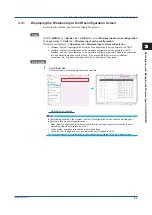
Page 116: ...ction manually resume and activate the GX70SM You cannot establish a connection with the GX70SM from this screen To do so use the Wireless input unit reconfiguration screen For details on wireless input unit reconfiguration see section 3 3 3 Reconfiguring Wireless Input Units on page 3 10 Path GX GP MENU key Browse tab Init Calib menu Wireless input unit info Web application Data tab Wireless inpu...

Page 117: ... and Descriptions See section 3 3 1 Displaying the Wireless Input Unit Reconfiguration Screen on page 3 5 Note The Wireless input unit info screen cannot be registered to the multi panel screen In the following situations the wireless input unit info screen cannot be displayed or registered to favorite and standard screens Under Basic configuration of Communication Serial settings the receiver fun...

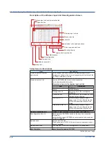
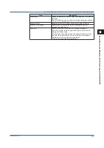
Page 118: ...me elapsed since the wireless coordinator received the GX70SM data HH MM SS RSSI The GX70SM RSSI value dBm Recognized unit Model of the recognized GX70SM Blank GX70SM 2 L0 Serial number of the recognized GX70SM Characters Connected unit Model of the connected GX70SM Blank GX70SM 2 L0 Serial number of the connected GX70SM Characters Input channel Communication channel number corresponding to the GX...

Page 119: ...s possible on the Wireless input unit reconfiguration screen and Wireless input unit info screen For details on how to switch to the Wireless input unit reconfiguration screen see section 3 3 1 Displaying the Wireless Input Unit Reconfiguration Screen on page 3 5 1 Select the option button for the GX70SM you want to maintenance The GX70SM individual operation buttons become available 2 Select Main...

Page 120: ...section 3 3 1 Displaying the Wireless Input Unit Reconfiguration Screen on page 3 5 1 Select the option button for the GX70SM you want to manually resume The GX70SM individual operation buttons become available Select a unit Manual resume 2 Select Manual resume A confirmation dialog box appears 3 Select OK The GX70SM disconnected from the wireless network will be restored Operation complete Note M...

Page 121: ...opouts This section explains how to clear the Modbus communication command dropout state A state in which the execution of a Modbus command could not be finished within the read cycle 1 Select the data dropout icon The dropout is acknowledged and the dropout icon disappears Dropout icon Operation complete 3 7 Controlling Wireless Input Units ...

Page 122: ...ion Division Bar graph Base position Division Partial ON Off Position Boundary Color scale band Band area Color Display position Lower Display position Upper Alarm point mark Indicate on Scale Mark type Alarm 1 color Alarm 2 color Alarm 3 color Alarm 4 color Calibration correction First unit number Last unit number Data type On Off On Off Mode Mode Number of set points 1 Linearizer input Linearize...

Page 123: ...play and channel information dialog box Data dropout alarm indication Example of an alarm summary Data dropout alarm indication For details on alarm summaries see the following manuals GX GP User s Manual Section 2 3 1 Listing the Log of Alarm Occurrences and Releases GM User s Manual Section 3 1 2 Monitoring the GM Data and Controlling the GM from the Monitor Screen Example of an overview Data dr...

Page 124: ...gh limit alarm L low limit alarm R high limit on rate of change alarm r low limit on rate of change alarm T delay high limit alarm t delay low limit alarm h difference high limit alarm l difference low limit alarm D data dropout For details on alarm notification mail see the following manuals GX GP User s Manual Section 1 21 4 Setting E mail Transmission Conditions When the SMTP client function is...

Page 125: ...er displays on the communication channel setup screen of each setup screen On the Web application auxiliary characters appear when you move the cursor over the selected component Auxiliary characters Example of a recording channel settings screen in recording settings Auxiliary Characters Data type Auxiliary characters Input 1 IN1 Input 2 IN2 Input 3 humidity sensor IN3 Higher data serial number H...

Page 126: ...gs Settings for wireless input units are loaded However the wireless input unit system information is not loaded Before loading the settings reconfigure the GX70SM For details on saving and loading settings see the following manuals GX GP User s Manual Section 1 25 Loading Settings Section 1 26 Saving Setting Parameters GM User s Manual Section 2 28 Saving and Loading Settings For details on recon...

Page 127: ...ialize all except communication settings GM10 only Security settings Control settings Other settings Internal data Wireless input unit info wireless input unit reconfiguration info Wireless input unit settings Includes calibration correction settings timeout settings and auto message printout settings Note When Initialize all is executed all the wireless input unit info will be cleared After initi...

Page 128: ... 2360 Display information block 224 Group information block 24 264 the number of groups Channel information block 24 328 the number of recording channels Calibration correction block 24 40 16 the number of set points the number of recording channels excluding math channels Wireless input unit system information 24 56 the number of wireless input units Time change information block 280 Measurement ...

Page 129: ...table shows the operation restrictions on the Wireless input unit reconfiguration and Wireless input unit info screens when logged in Logged in status Updating connection information Reconfiguring GX70SMs Manual resuming of disconnected GX70SMs Maintenance Pausing and resuming timeout detection Exchanged GX70SM Activation AS option Displaying detailed information dialog boxes Communication dropout...

Page 130: ...or Notification Mail Format Syntax fff Error number 234 501 502 507 511 611 619 692 693 695 696 698 699 848 921 For details on the system error notification format see the following manuals GX GP User s Manual System Error Notification Mail Format in section 3 2 5 E mail Format GM User s Manual System Error Notification Mail Format in section 3 2 5 E mail Format ...

Page 131: ...ode Title Description and Corrective Action Messages W8149 Initialize Appears when Initialize is executed from the menu bar GM only Initialize W8150 Reconfig all units Appears when Reconfiguration all units is executed from the Wireless input unit reconfiguration screen GM only Reconfigure all wireless units All relevant settings will be initialized Caution All current communication channel settin...

Page 132: ...GX GP GM detects this automatically WUFailed Unit number Serial number Manual resuming of disconnected GX70SMs WUResume Unit number Serial number GX70SM device change The GX GP GM detects this automatically WUChange Unit number Serial number before and after change Exchanged GX70SM activation WUActiv Unit number Unit number Setting changes during recording Changes to calibration correction set poi...

Page 133: ... 5 Displaying Logs GM User s Manual Section 3 1 2 Monitoring the GM Data and Controlling the GM from the Monitor Screen 4 9 2 Saving Setup Data If any of the wireless input unit settings shown below is changed when recording is paused a setup data file is saved in the SET0 folder in the GX GP GM SD memory The history is recorded in an event log and a new setting file is saved to an SD memory card ...

Page 134: ... possible on the Wireless input unit reconfiguration screen and Wireless input unit info screen Procedure 1 Select the option button for the GX70SM you want to activate Option button Activate 2 Select Activation A confirmation dialog box appears 3 Select OK The GX70SM is activated Operation complete Note Activation is possible while connection information is being updated or when the GX70SM has no...

Page 135: ... later 4 10 1 Performing Calibration Correction Procedure 1 Tap Wireless input unit settings on the setting menu A wireless input unit setting screen appears 2 Tap Calibration correction The calibration correction settings are displayed 3 Set the first unit number last unit number and data type 4 If necessary set the mode and the number of set points 5 Set the calibration correction of each set po...

Page 136: ...t unit reconfig Performing GM s wireless input unit reconfiguration 4 11 2 System Configuration 920 MHz wireless communication coordinator function and 920 MHz wireless communication router function are added to the system configuration options See step 7 in section 2 1 1 Creating a File in Accordance with System Configuration of the Hardware Configurator User s Manual Option name GX GP GM Default...

Page 137: ...GM functions Before editing the channel and display settings first create a file in accordance with the main unit s system configuration Procedure 1 Start the Hardware Configurator The setting screen appears 2 Click the Setting tab and then New A confirmation message is displayed that asks whether you want to save the displayed setup file 4 11 Hardware Configurator R4 02 and later ...

Page 138: ...reating a configuration file set the system configuration in accordance with the instrument first The System Config window can also be opened from System Config on the System tab If you change the system configuration the setup items that you have edited up to that point will be initialized 4 Set the main unit s system configuration Module Options GX GP firmware version GX10 GP10 tab Model 5 Click...

Page 139: ...sub revision are no longer displayed However if settings are received from the main unit or a configuration file created by the main unit is loaded the sub revision is displayed is not omitted Example R4 01 01 7 Set the items under Option The following table shows the 920 MHz wireless communication CM2 options For details on the support for other options see the Hardware Configurator User s Manual...

Page 140: ...ual Hardware Configurator Manual From step 8 in section 2 1 1 Creating a File in Accordance with System Configuration When you confirm the system configuration by clicking OK the default values related to the wireless input units will be the same as those shown in section 3 5 1 Auto Setup through Reconfiguration of All Units on page 3 23 Operation complete 4 11 Hardware Configurator R4 02 and late...

Page 141: ... Update all connection info and Reconfiguration all units at once It is not possible to perform only Update all connection info only Reconfiguration all units or individual unit operation 3 Click OK When the wireless input unit reconfiguration is complete a message appears Operation complete Note If user permission is set on the GM main unit only the following users can perform wireless input unit...

Page 142: ...t units Auxiliary Message always displayed Caution All current communication channel settings will be cleared Caution Proper setting is required when combining Logging Data created by wireless input unit with the original data files A confirmation displayed before execution when you click Wireless input unit reconfig on the Operation menu bar 4 11 Hardware Configurator R4 02 and later ...

Page 143: ...ogging data files and combined data files For details on the files that can be displayed and their extensions see the following manual Universal Viewer Manual Section 1 1 1 Files That Can Be Displayed and Their Extensions Logging data files and combined data files can be displayed on Universal Viewer version R3 05 and later If you are using an older version update to the latest version For details...

Page 144: ...aveforms For details on the circular display see the following manual Universal Viewer Manual Section 3 2 Displaying Waveforms on a Circular Chart For details on the digital display see the following manual Universal Viewer Manual Section 3 3 Displaying Digital Values For details on the list display see the following manual Universal Viewer Manual Section 3 4 Displaying a List of Alarms Marks and ...

Page 145: ...orms For details on the circular display see the following manual Universal Viewer Manual Section 3 2 Displaying Waveforms on a Circular Chart For details on the digital display see the following manual Universal Viewer Manual Section 3 3 Displaying Digital Values For details on the list display see the following manual Universal Viewer Manual Section 3 4 Displaying a List of Alarms Marks and Imag...

Page 146: ...Viewer Manual Section 3 6 Listing the Operation Log DX100P DX200P DX1000 DX1000N DX1000T DX2000 DX2000T with the AS1 option or GX10 GX20 GP10 GP20 GM10 with the AS option List of Operations by Model GX20 GP20 GM10 with AS option Wireless input unit disconnection Unit number All 1 to 96 Serial number serial number Type disconnect manual resume activation maintenance maintenance release reconfigurat...

Page 147: ... serial number after change Calibration correction mode point change for wireless unit Unit number All 1 to 96 Data type data 1 data 2 data 3 Serial number serial number Channel number CHC001 to CHC096 Mode Points Mode mode before change mode after change Points points before change points after change Calibration correction mode point change for wireless unit Unit number All 1 to 96 Data type dat...

Page 148: ...Blank ...

Page 149: ... SWDCom Watchdog timer MC Sets the watchdog timer of a communication channel The watchdog timer of channels that wireless input units are assigned to is fixed to Off 2 4 Setting Commands SWDCom Setting SAlarmCom Alarm MC Sets the alarm of a communication channel Data dropout alarm D is added to the alarm types of channels that GX70SMs are assigned to 2 4 Setting Commands SAlarmCom Setting SEventAc...

Page 150: ... data dropout D is added to the alarm types 2 5 Output Commands FFifoCur Output FStat Outputs the recorder status Outputs the recorder status Wireless error detected is added to status information 2 2 5 Output Commands FStat Output FLog Outputs the log Outputs the alarm summary message summary error log etc Wireless input unit data dropout D is added to the alarm types GX70SM operation is added to...

Page 151: ... List of Commands 6 2 1 Setting Commands Command Description Required Options Applicable Models Page Wireless Input Unit Setting Commands SWUnitTimeOut Wireless input unit timeout setting 6 3 SWUnitAutoMsg Wireless input unit auto message printout setting 6 3 Communication Channel Setting Commands Page SRangeCom Measuring range MC 6 3 SWDCom Watchdog timer MC 6 4 SAlarmCom Alarm MC 6 4 SCalibUseCo...

Page 152: ...rrespondence between channel numbers wireless unit s unit numbers and data types see Appendix 1 Communication Channel Assignments Based on Station Numbers and Data Types on page App 1 SAlarmCom Alarm MC Sets the alarm of a communication channel No Alarm Setting Syntax SAlarmCom p1 p2 p3 p1 Channel number p2 Alarm number 1 to 4 p3 Alarm on or off Off Do Not Output Alarms Syntax SAlarmCom p1 p2 p3 p...

Page 153: ...icient 9 p31 Input value of uncorrected value 10 p32 Instrument correction coefficient 10 p33 Sensor correction coefficient 10 p34 Input value of uncorrected value 11 p35 Instrument correction coefficient 11 p36 Sensor correction coefficient 11 p37 Input value of uncorrected value 12 p38 Instrument correction coefficient 12 p39 Sensor correction coefficient 12 Query SCalibCom p1 6 3 Setting Comman...

Page 154: ...ent details Operation Mode Device status Status WUnitErr Wireless input unit error Rising Falling Both For details on p7 to p11 see the Communication Command Manual SFailSts Instrument information to output FL CM2 GX GP Sets the instrument information to output from the fail relay DO channel Wireless input unit error is added to instrument information Syntax SFailSts p1 p2 p3 p4 p5 p6 p1 Memory me...

Page 155: ...s cannot be changed to other options Conditions that allow changing the setting while the function receiver is recording Before change After change After confirmation Change allowed Security function not available Security function available Off Off Master Yes No Master WirelessUnit Other than WirelessUnit No No The settings specified with this command take effect with the OSeriApply command The r...

Page 156: ... when the multi batch function BT is enabled When the multi batch function BT is not available p3 is fixed to 1 p1 cannot be set to BatchOverview when p3 is 1 to 12 When p3 All P1 cannot be set to Trend Digital Bar Alarm Message Memory or Multi When p1 is set to Trend Digital Bar Alarm Message Memory or Multi p3 cannot be set to All p3 cannot be set to 1 to 12 when p1 is set to BatchOverview Contr...

Page 157: ...imum number of blocks to read 1 to 9999 Example Read the measured data of channels 0001 to 0020 Set the read start position to 180 and the read end position to the most recent position Set the maximum number of blocks to read to 9999 FFifoCur 0 1 0001 0020 180 1 9999 Acquire the FIFO Data Read Range Syntax FFifoCur p1 p2 p1 FIFO read range output 1 p2 Scan group 1 or 2 Example Acquire the current ...

Page 158: ...t see section 6 6 4 Alarm Summary FLog on page 6 14 p3 is valid when multi batch is in use and p1 alarm msg event Omitting it is equivalent to specifying all batch groups FEventLog Outputs a Detail Event Log AS Outputs an event log You can specify the event user etc Syntax FEventLog p1 p2 p3 p4 p5 p1 Output format 0 The same output format as Flog EVENT no detailed information 1 Include detailed in...

Page 159: ...s Option Installation Information _OPT on page 6 18 _UNS or _UNR Outputs the instrument s unit configuration information Outputs the instrument s unit configuration information 920 MHz wireless communication option CM CS is added to the unit configuration information of the instrument Syntax _UNS Outputs the status that is recognized by the device _UNR Outputs the installation status Description F...

Page 160: ...crlf 095 cccccccccccccccc_uuuuuuuuuuuuuuuu crlf 096 cccccccccccccccc_uuuuuuuuuuuuuuuu crlf EN crlf nnn Wireless input unit number cccccccccccccccc Model name of the wireless input unit that is actually connected Wireless unit not installed 16 characters GX70SM Wireless input unit uuuuuuuuuuuuuuuu Model name of the wireless input unit that is recognized in the settings Wireless unit not installed 1...

Page 161: ...s level 1 a2 Alarm status level 2 a3 Alarm status level 3 a4 Alarm status level 4 a1 a2 a3 and a4 is set to one of the following H High limit alarm L Low limit alarm h Difference high limit alarm l Difference low limit alarm R High limit on rate of change alarm r Low limit on rate of change alarm T Delay high limit alarm t Delay low limit alarm D Wireless input unit data dropout alarm Space No ala...

Page 162: ...dule or when a burnout has occurred 7 Communication error Set to 1 when a Modbus master Modbus client WT communication or SLMP communication error has occurred 6 6 4 Alarm Summary FLog The output in response to the command FLog ALARM is shown below Wireless input unit data dropout is added to the alarm types See section 2 10 9 Alarm Summary FLog in the Communication Command Manual Syntax ss Alarm ...

Page 163: ...e security function AS is enabled Operation Event string information and detailed information Information is included in Blue text indicates the detailed information output format Setting changes during recording Calibration correction set point change for communication channels SetComCCMode Pnt uuu dd cccc ssssssssss mode num b1 b2 a1 a2 u Unit number 0 No GX70SM assignment d Data type 1 2 3 0 No...

Page 164: ...gs input Calibration correction before change output Output calibration value before and after change Example 001 02 03 C001 S12345678 output 1 234 2 234 Calibration correction value change for communication channels SetCom Action output in the event string CFactor Correction factor uuu pp dd cccc ssssssssss uncorrected instru se nsor b1 b2 b3 a1 a2 a3 u Unit number 0 No GX70SM assignment p Correc...

Page 165: ...u Unit number ALL for all units s Serial number Wireless input unit mode Action output in the event string MaintHalt uuu unit number uuu s s u Unit number ALL for all units s Serial number Wireless input unit mode Action output in the event string MaintResume uuu unit number uuu s s u Unit number ALL for all units s Serial number Wireless input unit activation WU uuu Action output in the event str...

Page 166: ...M 920 MHz wireless communication coordinator function CS 920 MHz wireless communication router function 6 6 8 Instrument s Unit Configuration Information _UNS or _UNR The output in response to the command _UNS or _UNR is shown below The installation information of the 920 MHz wireless communication CM CS option is added to the unit option information output See section 2 10 46 Instrument s Unit Co...

Page 167: ...w limit alarm 3 Difference high limit alarm 4 Difference low limit alarm 5 High limit on rate of change alarm 6 Low limit on rate of change alarm 7 Delay high limit alarm 8 Delay low limit alarm 9 Wireless input unit data dropout alarm 6 0 No alarm is activated 1 An alarm is activated 7 0 Alarm nonhold state 1 Alarm hold state 6 7 2 Channel FIFO Data FFifoCur The output in response to the command ...

Page 168: ...Blank ...
Page 169: ...118 Input 3 C019 C069 C119 Higher data serial number C020 C070 C120 Lower data serial number 5 C021 15 C071 25 C121 Input 1 C022 C072 C122 Input 2 C023 C073 C123 Input 3 C024 C074 C124 Higher data serial number C025 C075 C125 Lower data serial number 6 C026 16 C076 26 C126 Input 1 C027 C077 C127 Input 2 C028 C078 C128 Input 3 C029 C079 C129 Higher data serial number C030 C080 C130 Lower data seria...

Page 170: ...C272 Input 2 C173 C223 C273 Input 3 C174 C224 C274 Higher data serial number C175 C225 C275 Lower data serial number 36 C176 46 C226 56 C276 Input 1 C177 C227 C277 Input 2 C178 C228 C278 Input 3 C179 C229 C279 Higher data serial number C180 C230 C280 Lower data serial number 37 C181 47 C231 57 C281 Input 1 C182 C232 C282 Input 2 C183 C233 C283 Input 3 C184 C234 C284 Higher data serial number C185 ...

Page 171: ... 1 C322 C372 C422 Input 2 C323 C373 C423 Input 3 C324 C374 C424 Higher data serial number C325 C375 C425 Lower data serial number 66 C326 76 C376 86 C426 Input 1 C327 C377 C427 Input 2 C328 C378 C428 Input 3 C329 C379 C429 Higher data serial number C330 C380 C430 Lower data serial number 67 C331 77 C381 87 C431 Input 1 C332 C388 C432 Input 2 C333 C383 C433 Input 3 C334 C384 C434 Higher data serial...

Page 172: ...nput 1 C462 Input 2 C463 Input 3 C464 Higher data serial number C465 Lower data serial number 94 C466 Input 1 C467 Input 2 C468 Input 3 C469 Higher data serial number C470 Lower data serial number 95 C471 Input 1 C472 Input 2 C473 Input 3 C474 Higher data serial number C475 Lower data serial number 96 C476 Input 1 C477 Input 2 C478 Input 3 C479 Higher data serial number C480 Lower data serial numb...

Page 173: ...es standard operating conditions standard mode Power supply through the USB port is also possible Extensive self diagnostics function is available Device errors such as drop in the battery voltage and errors in the input can be detected Wireless Input Unit Configurator software can be used to configure and perform maintenance on wireless input units Further the logging data of the wireless input u...

Page 174: ... to 1820 0 C N 1 270 0 to 1300 0 C 0 15 of rdg 0 7 C However 200 0 to 0 0 C 0 35 of rdg 0 7 C Accuracy not guaranteed for temperatures less than 200 0 C 0 3 of rdg 3 5 C However 200 0 to 0 0 C 0 7 of rdg 3 5 C Accuracy not guaranteed for temperatures less than 200 0 C WRe3 25 2 0 0 to 2400 0 C 0 2 of rdg 2 5 C Except 0 0 to 200 0 C 4 0 C 0 3 of rdg 10 0 C Except 0 0 to 200 0 C 18 0 C RTD Pt100 3 2...

Page 175: ...ignal Allowable wiring resistance 10 Ω or less per line the same resistance for all three lines for RTD Effect of wiring resistance 0 1 C 10 Ω the same resistance for all three lines for RTD Effects of ambient temperature Fluctuation per 10 C change DCV TC range Within 0 1 of rdg 0 05 of range reference junction compensation accuracy not included RTD range Within 0 1 of rdg 0 2 C Allowable input v...

Page 176: ... temperature and vibration USB power Compatible USB AC DC adapter 5 V DC 5 500 mA Connector USB2 0 mini B connector Wireless Function Specifications Carrier frequency band 902 1 MHz to 927 9 MHz Frequency band 600 KHz Number of wireless channels 43ch Maximum transmission output 20 mW Wireless data rate approx 100 kbps Modulation method GFSK Communication format Mesh connect up to 100 units includi...

Page 177: ...on IP20 Connector 7 pin clamp terminal Installation methods Wall mount fastened with screws hooked on a desktop mounted with the magnet Color Smoke gray Munsell 4 1PB 6 0 4 5 equivalent External dimensions 90 W x 90 H x 32 D mm Weight Approx 300 g External Dimensions 90 3 54 32 1 26 9 55 90 3 54 Unit mm Unless otherwise specified tolerance is 3 however tolerance is 0 3 mm when below 10 mm 0 38 98 ...

Page 178: ...imes turns off for 2 seconds and repeats the entire sequence For example configuring in a mode other than measurement mode when there is no USB connection Self diagnosis function Transmits the following device status to the coordinator Low battery warning Low battery voltage detected Critical low battery warning Minimum drive voltage detected Batteries must be replaced quickly Input error Calibrat...

Page 179: ...ta and the data during the missing period can be verified Logging data file Wireless input unit Recording data file GX20 GP20 GM10 File combining Combined data file Logging data and combined data files can be viewed on SMARTDAC Universal Viewer Note Power supply form USB is required during wireless input unit configuration Use a powered USB cable PC System Requirements OS OS Type Windows 7 Home Pr...

Page 180: ...ber of technically possible connections varies depending on the wireless communication condition and the measurement transmission interval Auto configuration function Automatically configures the wireless input unit data collection settings Wireless data dropout detection function Detects data collection dropouts due to wireless communication errors or the like Management monitoring and maintenanc...

Page 181: ...are from the following URL URL www smartdacplus com software en User s Manual You can download the product user s manuals from the following URL You will need Adobe Reader 7 or later latest version recommended by Adobe Systems URL www smartdacplus com manual en 920 MHz wireless communication devices Coordinator GX20 Paperless Recorder CM2 MC option GS 04L51B01 01EN GP20 Paperless Recorder CM2 MC o...

Reviews: