background image

IM 12D07K04-01EN-P

19

Figure 10: 

Option /FA

Alternative ways of mounting the immersion fitting are: 

• 

Guide pipe 

To facilitate this type of mounting the immersion fitting has a larger diameter at the 

top. The user supplied guide pipe (internal diameter > 52 mm) is fitted to the wall 

or mounting rail. The immersion fitting slides into this guide pipe and therefore the 

sensor can be easily removed for inspection. 

• 

Platform mounting 

Sometimes there is a walking platform that can be used to mount the immersion 

fitting. The top of the immersion fitting has a larger diameter than the shaft. The only 

thing to do is to drill a precise hole in the platform to slide the fitting through.

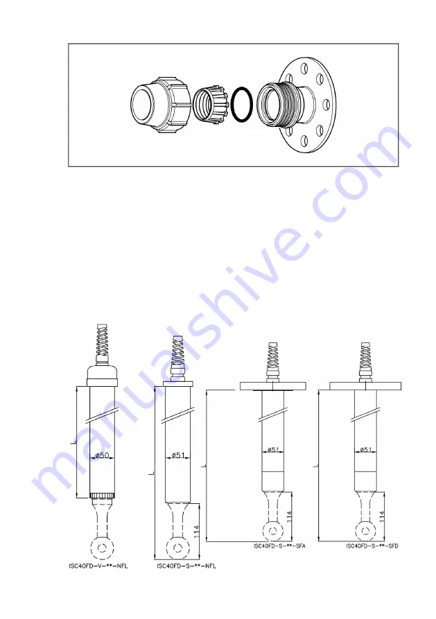
4.3 DIMENSIONS ISC40FD

Figure 11: 

Immersion fitting ISC40FD

Dimensions in mm

Summary of Contents for ISC40FD

Page 1: ...User s Manual Model ISC40FF ISC40FS ISC40FD Sensor fitting IM 12D07K04 01EN P 1st edition...

Page 2: ...IM 12D07K04 01EN P 2...

Page 3: ...FS FLOW FITTING SUBASSEMBLY 12 3 1 General Specifications 12 3 1 1 Materials 12 3 1 2 Operating range 12 3 1 3 Shipping details 12 3 1 4 Process connections 12 3 2 INSTALLATION OF ISC40 SENSOR IN ISC4...

Page 4: ...d and correct 1 3 Warranty and Service Yokogawa products and parts are guar anteed free from defects in workman ship and material under normal use and service for a period of typically 12 months from...

Page 5: ...P400123 Table 1 Production Year code Year Year code Year Year code 2014 P 2026 3 2015 R 2027 4 2016 S 2028 5 2017 T 2029 6 2018 U 2030 7 2019 V 2031 8 2020 W 2032 9 2021 X 2033 A 2022 Y 2034 B 2023 Z...

Page 6: ...perature Model ISC40FF P 1 Max 6 bar 90 PSI at 20 C 68 F Max 1 bar 15 PSI at 100 C 212 F Model ISC40FF F 1 Max 10 bar 150 PSI at 20 C 68 F Max 1 bar 15 PSI at 130 C 266 F 2 1 3 Shipping details Withou...

Page 7: ...is upwards to assure complete filling of the flow chamber Installation of the fitting on wall railing or stanchion For this purpose the flow fitting has an optional pipe wall mounting kit MS or MP se...

Page 8: ...ISC40FF P ISC40FF F Stainless steel Stainless steel Stainless steel Stainless steel Dimensions in mm inches FF1 PVDF FP1 Polypropylene ISC40FF FA ISC40FF PA FF2 PVDF FP2 Polypropylene FF3 PVDF FP3 Pol...

Page 9: ...9 IM 12D07K04 01EN P Figure 4 Flow fitting ISC40FF S Flange wall distance ISC40FF SA FS1 SS FS2 SS FS3 SS FS4 SS...

Page 10: ...PVDF DN25 PN10 flange adapters FF3 PVDF 150lbs flange adapters FF4 PVDF 1 150lbs flange adapters FP1 PP DN15 PN10 flange adapters FP2 PP DN25 PN10 flange adapters FP3 PP 150lbs flange adapters FP4 PP...

Page 11: ...Flow fitting Part no Description Dimensions Material O ring s K1541KD Holder O rings 2 PVDF Viton K1541KL Holder O rings 2 Polypropylene Viton K1541KA Holder O rings 2 AISI 316 SS Viton Note Other O r...

Page 12: ...15 PSI at 130 C 266 F Model ISC40FS PCSA Max 6 bar 90 PSI at 20 C 68 F Max 1 bar 15 PSI at 100 C 212 F Model ISC40FS SCSA Max 10 bar 150 PSI at operating temperature Model ISC40FS SCWN Max 10 bar 150...

Page 13: ...ies Generally the subassembly consists of three parts of which one part is fitted perma nently to the process installation welded or threaded the second part is fitted to the sensor and the third part...

Page 14: ...IM 12D07K04 01EN P 14 3 3 DIMENSIONS Figure 7 Dimensions ISC40FS with sensor installed dimensions in mm inches Dimensions in mm inches...

Page 15: ...ty flow fitting subassembly Material F Polyvinylidenefluoride PVDF P Polypropylene PP S Stainless steel SS Process connection CS 2 coupling screw in CW coupling weld acc to DIN 11851 only for S Screw...

Page 16: ...3 53 56 52 x 5 33 EPDM 5 sets K1500DE O ring set 40 64 x 5 33 26 57 x 3 53 56 52 x 5 33 Viton 5 sets K1500DG O ring set 40 64 x 5 33 26 57 x 3 53 56 52 x 5 33 Silicon 5 sets K1500CD O ring 40 64 x 5 3...

Page 17: ...at operating temperature Model ISC40FD V Max 2 bar 30 PSI at 20 C 68 F Max 1 bar 15 PSI at 80 C 176 F 4 1 3 Shipping details Package size LxWxH and Package weight max is dependable on fitting length 4...

Page 18: ...pipe clamp The second pipe clamp connects the guide pipe to the immersion fitting The distance between the pipe clamps deter mines the distance between the stanchion and immersion fitting see Figure...

Page 19: ...or mounting rail The immersion fitting slides into this guide pipe and therefore the sensor can be easily removed for inspection Platform mounting Sometimes there is a walking platform that can be us...

Page 20: ...IM 12D07K04 01EN P 20 Figure 14 Protection hose option PH5 PH10 Figure 12 Pipe mounting set option MS1 Figure 13 Adjustable flange option FA...

Page 21: ...ter 6 0 6 m 7 0 7 m 8 0 8 m 9 0 9 m 10 1 0 m 11 1 1 m 12 1 2 m 13 1 3 m 14 1 4 m 15 1 5 m 16 1 6 m 17 1 7 m 18 1 8 m 19 1 9 m 20 2 0 m Flange SFD AISI316 SS DN50 SFA AISI316 SS 2 NFL No flange Options...

Page 22: ...ion Dimensions O rings S Material Quantity K1500CE O ring set 39 35 x 2 62 26 57 x 3 53 EPDM 5 sets K1500CF O ring set 39 35 x 2 62 26 57 x 3 53 Viton 5 sets K1500CG O ring set 39 35 x 2 62 26 57 x 3...

Page 23: ...5 CHEMICAL COMPATIBILITY IM 12D07K04 01EN P 23 Table 6 Chemical compatibility chart...

Page 24: ...Subject to change without notice Copyright Printed in The Netherlands 01 2202 IM 12D07K04 01EN P...

Reviews: