2-2
IM 71M02D04-01E 10th Edition: 2012.12.01
•
Be sure the mounting screws of a load to the slider never reach or exceed the effective
screw depth of the slider.
•
The motor accuracy depends on the accuracy of the surface to which the mounting
plate is attached. The surface accuracy affects the accuracy, lifetime, etc., of
LINEARSERV. Therefore, the mounting plate should be mounted on a surface as
accurate as possible. As a general guideline, use a reference value of 0.01 mm or less
per 1000 mm of the motor’s stroke length for the levelness of the mounting surface.
•
Remove any burrs, dents, dirt and so forth from the surface on which the motor unit is
mounted, and then place the motor unit on it carefully. Tighten the motor unit mounting
bolts in the order from the center to both sides following the mounting surface. If the
order of tightening the bolts is inappropriate or the bolts are tightened excessively, the
motor unit may become deformed and accuracy may be impaired.
Stopper and Shock Absorption
The stopper in the motor is not intended to absorb impact during operation. If the stopper is
subjected to shock when mounting a load, the LINEARSERV and connected devices may be
damaged or broken. Carefully mount an external safety stopper, impact-absorbing
mechanism or similar device in order to avoid impact while the motor is operating, stopped or
in transit. Please prepare separate equipment for protection/safety procedures, such as a
stopper and shock absorber.
Fixing Cables on the Slider
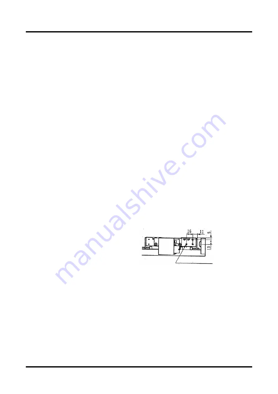
There are power and encoder cables exiting the connector parts at two places on the slider.
During installation, fix the cables on the slider’s side surface. Screw holes for that purpose
are located on the slider's side surface. (See the figure below in the case of <LM105>, where
cables are taken out to the right, or see the external appearance diagram for other models.)
The connectors in the slider are for connecting the power cable and encoder cable. Prepare
a fixture on the load side for the cables connected to the connectors of the slider, or fix them
on the slider side using the cable attachment screws of the slider, etc., so that external force
is not applied to the connectors. Failure to do so may lead to disconnection or breakdown.
<In the case of the LM105 model, where cables are taken out to the right>
3-M3, depth 5


