<4. WIRING>
4-3
IM 11P03A03-01E
6th Edition : Jan. 26, 2022-00
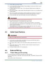
The ground resistance should be 100 Ω or less. The jumper plate between terminals G (26) and
FG (27) must remain connected.
FG terminal is functional earth terminal.
4.4.2
Analog Output Wiring
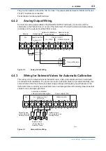
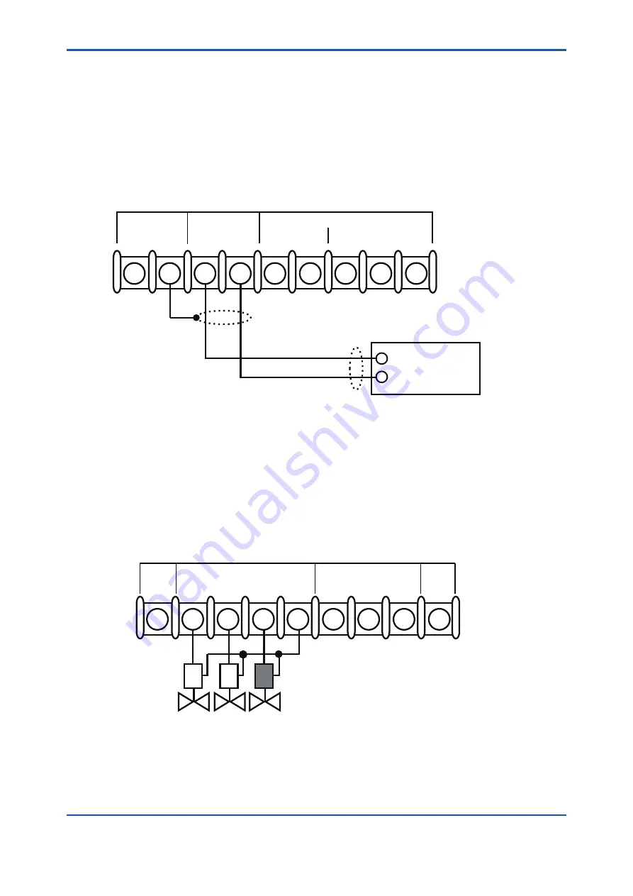
Connect an analog output cable to the ANALOG OUTPUT terminals, (3) and (4), and the
shield wire to the FG terminal, (1) or (2), of the instrument. The load resistance including wiring
resistance on the output should be 550 Ω or less.
1
2
3
4
5
6
7
8
9
FG
CAL START
4-20mA DC
COM
R3
R2
RANGE CHANGE
ANALOG OUTPUT
CONTACT INPUT
+
+
–
–
Shield
F7.2E.ai
Receiver/Recorder
Output signal
Automatic calibration
contact input
Ground
Remote range
contact input
Figure 4.2
Analog Output Wiring
4.4.3
Wiring for Solenoid Valves for Automatic Calibration
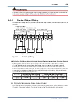
This wiring is for the solenoid valves that switch zero, span, and sample gas lines in automatic
or semiautomatic calibration. The power sources for solenoid valves are provided internally. Use
solenoid valves that have the same power supply voltage and frequency specifications as the
instrument. Use a normally open solenoid valve in sample gas line and normally closed solenoid
valves for zero and span gas lines.
25
26
F7.3E.ai
27
FG
ZERO SPAN
SMPL
COM
L
N
G
FG
SV POWER OUTPUT
AUTO CAL
POWER SUPPLY
19
20
21
22
23
24
Solenoid Valve
in Sample Gas Line,
Normally Open
Solenoid Valve
in Span Gas Line,
Normally Closed
Solenoid Valve
in Zero Gas Line,
Normally Closed
Automatic calibration
solenoid valve drive signal
Power supply (AC)
Figure 4.3
Solenoid Valve Wiring
Summary of Contents for MG8E
Page 5: ...Blank Page...
Page 9: ...Blank Page...
Page 13: ...Blank Page...
Page 17: ...Blank Page...
Page 21: ...Blank Page...
Page 27: ...Blank Page...
Page 61: ......
Page 63: ...Blank Page...


