background image


<4.  WIRING>

4-5

IM 11P03A03-01E

6th Edition : Jan. 26, 2022-00

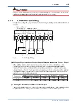
(c) Wiring for Fail Contact Output

The contact between terminals 15 and 16 will be activated when an error occurs. The output 

contact is user configurable to be normally energized (the contact will open when an error 

occurs) or normally deenergized (the contact will close when an error occurs). For the setting and 

functions, refer to Chapter 8, Parameter Settings. The contact is open when the instrument is not 

powered.

4.4.5 

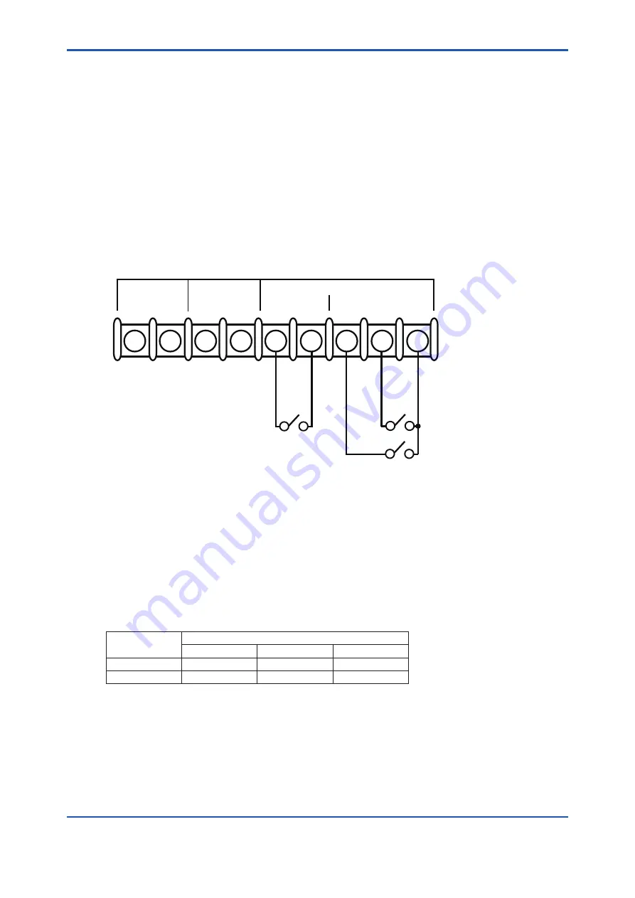
Contact Input Wiring

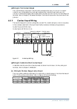
The input is designed to accept a voltage free contact. The contact will open or close in response 

to the resistance detected on the input. Note that the resistance includes wiring resistance.

Contact closes at 200 Ω or less
Contact opens at 100 kΩ or more


1  

2  

3  

4  

6

FG 

CAL START 

4-20mA  DC 

COM 

R3 

R2 
 

RANGE CHANGE 

ANALOG OUTPUT 

+


CONTACT INPUT  

F7.5E.ai

Output signal

Automatic calibration

contact input

Ground

Remote range 

contact input

Figure 4.5 

Contact Input Wiring

(a) Wiring for Calibration Start Contact Input

A calibration will start when the contact between terminals 5 and 6 closes. For the setting and 

functions, refer to Chapter 9, Calibration.

(b)  Wiring for Remote Range Contact Input

The range will be switched externally by the state of the contacts between 7 and 9 and between 8 

and 9. For the setting and functions, refer to Chapter 8, Parameter Settings.

Terminal No.

Remote Range Contact Input

Range 1

Range 2

Range 3

7-9

Open

Open

Closed

8-9

Open

Closed

Open

Summary of Contents for MG8E

Page 1: ...User s Manual Model MG8G Paramagnetic Oxygen Analyzer IM 11P03A03 01E IM 11P03A03 01E 6th Edition...

Page 2: ...kg Handle it with care Be sure not to accidentally drop it Handle it safely to avoid injury l Check of Model Name and Specifications The nameplate on the inside of the converter door shows the main i...

Page 3: ...cial care the operator must take to avoid such risks CAUTION This symbol indicates that the operator must refer to the instructions in this manual in order to prevent the instrument hardware or softwa...

Page 4: ...that some of the images contained in this user s manual are display examples n Warning and Disclaimer The product is provided on an as is basis YOKOGAWA shall have neither liability nor responsibility...

Page 5: ...Blank Page...

Page 6: ...2 4 4 External Wiring 4 2 4 4 1 Power Wiring and Grounding 4 2 4 4 2 Analog Output Wiring 4 3 4 4 3 Wiring for Solenoid Valves for Automatic Calibration 4 3 4 4 4 Contact Output Wiring 4 4 4 4 5 Conta...

Page 7: ...3 8 6 Setting the Range Switching Answerback Contact Output 8 4 9 CALIBRATION 9 1 9 1 Overview 9 1 9 2 Calibration Coefficient 9 1 9 2 1 Zero Calibration Coefficient 9 1 9 2 2 Span Calibration Coeffic...

Page 8: ...Faulty Readings During Measurement 12 3 12 2 1 Fluctuations in Readings 12 3 12 2 2 Drift in Readings 12 3 12 2 3 Short Term Shift in Readings 12 3 12 3 When Calibration Cannot Be Executed 12 4 12 4 I...

Page 9: ...Blank Page...

Page 10: ...etween the input and output sections Further the instrument is provided with one touch calibration and self test functions to improve operability maintainability and reliability n Standard System Conf...

Page 11: ...e Pressure gauge Analog output Contact output Contact input Power supply Atmosphere vent Sampling gas Auxiliary gas Filter Flow meter Flow control valve Zero gas Span gas Figure 1 2 System Configurati...

Page 12: ...N ZERO FUNC MEAS MAINT DECIMAL POINT SHIFT INCR EXEC PARAMAGNETIC OXYGEN ANALYZER FUNC HEATER AUTO CAL MRT RANGE AUTO RANGE LCL RANGE MEANS MAINT H ALM L ALM FAIL DATA OUT PUT vol O2 Operation keys F5...

Page 13: ...Blank Page...

Page 14: ...and measured gas Maximum load AC 1A Contact input Input specification Contact ON 200 or less Contact OFF 100 k or greater Remote range switching 2 points Output ranges 1 to 3 can be switched by exter...

Page 15: ...tegory II Pollution degree 2 Note Installation category called overvoltage category specifies impulse withstand voltage Pollution degree indicates the degree of existence of solid liquid gas or other...

Page 16: ...quest as a Customized Order STANDARD ACCESSORIES Item Parts No Qty Description Fuse A1111EF 2 250V 2A Spanner G7050YZ 1 for adjustment of sensor angle Regulator G7033XF 1 for Auxiliary gas Mirror K932...

Page 17: ...Blank Page...

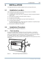
Page 18: ...nd wherever possible do not install the analyzer near motor electromagnetic relays pumps etc 7 Easy access for maintenance and inspection 3 2 Installation Procedure This oxygen analyzer can be panel o...

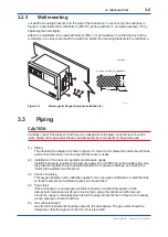
Page 19: ...ty by components of the sample gas 1 Piping The standard line diagram is shown in figure 3 3 Use 6 4 mm diameter metal tubes for lines and connect the tubes in such a way that there are no leaks 2 Ins...

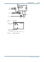
Page 20: ...le gas Auxiliary gas Filter Flow meter Flow control valve Pressure gauge Pressure regulator F6 1E ai 180 kPa Figure 3 3 Line Diagram Purge air outlet with blind seal Purge air inlet Rc 1 8 female thre...

Page 21: ...Blank Page...

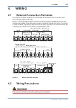
Page 22: ...y a supplied jumper plate 1 2 3 4 5 6 7 8 9 FG CAL START 4 20mA DC COM R3 R2 RANGE CHANGE ANALOG OUTPUT CONTACT INPUT 10 11 12 13 14 15 16 17 18 R3 HI MAIT CAL FAIL R2 LO COM RANGE OUT HL ALM CONTACT...

Page 23: ...reaker conforming with IEC 60947 1 or IEC 60947 3 3 It is recommended that the external switch or circuit breaker be mounted into the equipment which the product is installed 4 The external switch or...

Page 24: ...act input Figure 4 2 Analog Output Wiring 4 4 3 Wiring for Solenoid Valves for Automatic Calibration This wiring is for the solenoid valves that switch zero span and sample gas lines in automatic or s...

Page 25: ...Contact Output Either high low alarm contact output or range answerback contact output can be selected For their detailed functions and setting procedures refer to Chapter 8 Parameter Settings Termin...

Page 26: ...ut Note that the resistance includes wiring resistance Contact closes at 200 or less Contact opens at 100 k or more 1 2 3 4 5 6 7 8 9 FG CAL START 4 20mA DC COM R3 R2 RANGE CHANGE ANALOG OUTPUT CONTAC...

Page 27: ...Blank Page...

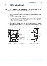
Page 28: ...ing the adjustment screw counterclockwise brings the bubble position toward the front of the instrument 5 Tighten the four bolts with the wrench Make sure that the bubble is in position 6 Replace the...

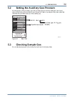
Page 29: ...is indicated on the name plate on the inside of the instrument door Figure 5 2 shows an example of the name plate that indicates the specified pressure of the auxiliary gas SUFFIX MA 5 WL JN C F0502...

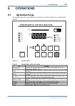
Page 30: ...EXEC key to switch measurement MEAS mode and maintenance MAINT mode SPAN Used to execute span calibration in calibration Used to enter span gas concentration in setting ZERO Used to execute zero cali...

Page 31: ...gas is selected in calibration gas concentration setting Blinks when span calibration is required ZERO Lights when zero calibration is selected in calibration Lights when zero gas is selected in calib...

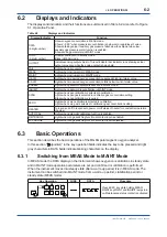
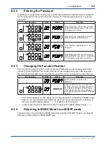
Page 32: ...3 Changing the Function Number Each function is assigned to the Function Numbers Parameters can be viewed and set in the relevant Function Number The Function Number can be changed using the FUNC keys...

Page 33: ...s dependent on the specifications ENABL INHIBIT SPAN ZERO FUNC DECIMAL POINT SHIFT INCR EXEC MEAS MAINT Press SHIFT key The leftmost digit of 2 blinks indicating that the digit can be changed ENABL IN...

Page 34: ...on FUNC display DATA display shows 1 the currently selected range ENABL INHIBIT SPAN ZERO FUNC DECIMAL POINT SHIFT INCR EXEC MEAS MAINT Press SHIFT key 1 blinks indicating that the digit can be chang...

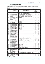
Page 35: ...0 to 25 O2 22 Setting high low limit alarm function 0 disabled 1 enabled 30 Checking temperature C of constant temperature chamber 31 Checking sensor emf mV 40 Executing error check 41 Resetting senso...

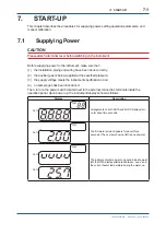
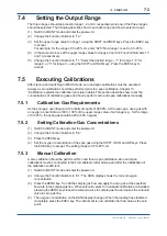
Page 36: ...ied pressure 3 the supply voltage meets the instrument specifications and 4 no sample gas has been introduced Then turn on the power switch located next to the external connection terminals inside the...

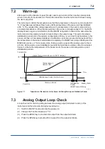
Page 37: ...ized A calibration cannot be executed in this period When the temperature in the sensor unit stabilized completely the MAINT lamp stops blinking and the MEAS lamp turns on This is steady state During...

Page 38: ...tion Gas Requirements As the zero gas use nitrogen with a minimum purity of 99 99 As the span gas use a gas with an oxygen concentration of 80 to 100 of the upper range value of set range e g for the...

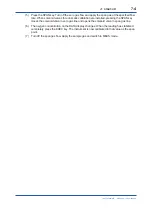
Page 39: ...calibration are installed pressing the SPAN key closes the solenoid valve in zero gas line and opens the solenoid valve in span gas line 6 The oxygen concentration on the DATA display changes When the...

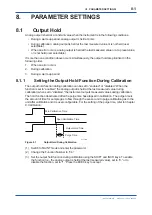
Page 40: ...set to enabled or disabled When the function is set to enabled the analog output is held at the last measured value during calibration when set to disabled the instrument outputs measured values durin...

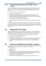
Page 41: ...e INCR key repeatedly to increase the blinking number 0 1 2 9 and returns to 0 8 2 Setting the Fail Contact The Fail contact terminals 15 and 16 is activated when an error occurs The contact can be pr...

Page 42: ...ct is activated when the measured value is equal to or higher than the high alarm setpoint or when the measured value is equal to or less than the low alarm setpoint The alarm contact does not operate...

Page 43: ...sed when the high low limit alarm function is enabled 1 Switch to MAINT mode and enter the password 2 Change the Function Number to 22 3 Set to 0 to disable the high low limit alarm function using the...

Page 44: ...cs is obtained from the following equation cs k ps p1 Calibration is for obtaining k When only a zero calibration is performed the instrument is calibrated to the zero gas s value and the ratio of the...

Page 45: ...to 05 The DATA display shows rES 3 Press the EXEC key to initialize the calibration coefficients CAUTION The calibration coefficients disolayed in Function No 03 are still the previous ones after the...

Page 46: ...rt calibration when the dry voltage free contact connected to the input is closed For the semiautomatic calibration the following should be set 1 Zero calibration time Function No 52 The amount of tim...

Page 47: ...ter the automatic calibration function was started The setting range is from 0 day 0 hour to 99 days 24 hours When the time is set to 00 day 00 hour the initial wait time is equal to the time set as t...

Page 48: ...sired interval using the SHIFT and INCR keys Press the EXEC key to accept 6 Change the Function Number to 55 to set whether or not to execute span calibration Set to 0 not to execute span calibration...

Page 49: ...tion is enabled After power is restored calibrations will be executed on schedule there is no delay due to the power interruption Note that the internal timer does not work when the power supply is in...

Page 50: ...ssword 2 Change the Function Number to 58 The DATA display shows an oxygen concentration 3 Press the ZERO key to open the solenoid valve in zero gas line and close the solenoid valve in sample gas lin...

Page 51: ...30 Checking temperature C of constant temperature chamber 31 Checking sensor emf mV 40 Executing error check 41 Resetting sensor emf error status 42 Resetting calibration coefficient error status 43 S...

Page 52: ...and Restarting the Operation The most common failure or trouble occurs when stopping or restarting the operation Extreme care should be taken 1 When sample gas contains corrosive components turn off...

Page 53: ...fuse deteriorates with time It is recommended that the fuses be replaced every two years even if the fuse has not blown CAUTION If the fuse blows again soon after replacement there may be a malfuncti...

Page 54: ...E 20 In stabilization period or steady state heater temperature continues to fall below 55 C for at least 10 seconds Turn off power to heater Remove the causes Turn the power off and on again to resta...

Page 55: ...wer supply voltage fluctuates 2 The ambient temperature is outside the specification range 5 to 55 C n Constant Temperature Chamber Errors E 22 E 23 A constant temperature chamber error E 22 or E 23 o...

Page 56: ...drift or characteristics change with time initialize the calibration coefficients and perform zero and span calibration again When the error occurs during semiautomatic or automatic calibration remove...

Page 57: ...ailure is 80 ms or shorter in the case of the instrument with a power supply of 100 to 115 V AC or if the duration of power failure is 350 ms or shorter in the case of the instrument with a power supp...

Page 58: ...Constant resistance circuit Constant resistance circuit Figure 13 1 Measurement Principle 13 2 Principle of Interference gas Compensation Although measurements by the paramagnetic oxygen analyzer uti...

Page 59: ...se the inclination is stored using a built in level containing a bubble in a glass tube When this analyzer is installed at the user s site turning the rotary knob so that the bubble of this level retu...

Page 60: ...List MG8G Paramagnetic Oxygen Analyzer CMPL 11P03A03 01E 1st Edition Feb 2016 YK 1 Item Part No Qty Description 1 A1111EF 2 Fuse All Rights Reserved Copyright 2016 Yokogawa Electric Corporation Subjec...

Page 61: ......

Page 62: ...ll review Nov 2008 4th Edition Revised and style change from B to C Aug 2007 3rd Edition Revised and Corrected over all e g After Sales Warranty Revision Information etc are added IM Format and Style...

Page 63: ...Blank Page...

Reviews: