1-9
TI 77C01H01-01EN
Oct. 17, 2018-00
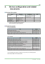
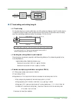
6600
VAC
500
AAC
6600VAC
Settings: VT ratio 60, CT ratio 100
Power monitor
110VAC
500AAC
5AAC
VT
CT
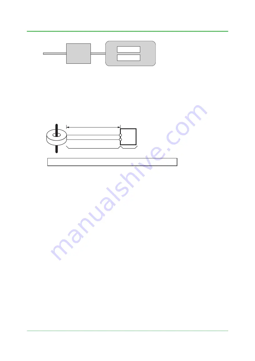
CT load rating and wiring length
●
CT load rating
For the rated load, use a value within the sum of the wiring loss between the CT and the device
connected to the secondary side, and the input loss to the device connected to the secondary
side. The load rating notation could be, for example, “0.5 VA, 2.5 VA.”
CT
CT rated load
≧
wiring loss + input loss of device connected to the secondary side
To calculate wiring loss, see “Checking the wiring distance and material” and
“Detailed example (approximation using the CTW10).”
Wiring distance
Connected device
Device input loss
Wiring loss
●
Checking the wiring distance and material
The wiring loss increases in proportion with the wiring distance. The total wiring length is the
round trip distance.
Approximate wiring material resistance (ex.)
Nominal cross section 1.25 mm = approx. 18 Ω/km
Nominal cross section 2.0 mm = approx. 10 Ω/km
●
Detailed example (approximation using the CTW10)
CT: Primary/secondary rated current: 100 A/1A
CT load rating: 0.5 VA
Wiring distance: 15 m, input loss of device connected to secondary side: 0.2 VA
• When using wiring material of nominal cross section 1.25 mm
2
Wiring resistance R = 18 Ω/km × 0.015 km × 2 (round trip) = 0.54 Ω
Wiring loss ≈ I
2
R = (second. rated current)
2
× wiring resistance = 1 × 1 × 0.54 = 0.54 VA
Condition: CT rated load ≥ wiring loss + input loss of device cnctd. to secondary side
0.5 ≥ 0.54 + 0.2 = 0.74 VA
This does not meet the condition.

