1-11
TI 77C01H01-01EN
Oct. 17, 2018-00
P1
P2
P3
1S
1L
3S
3L
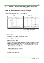
(1)(2)(3)
(1)(2)(3)
(4)
3 phase 3 wire
R
S
T
FUSE
FUSE
Power supply
Load
k
K
K
l
L
L
k
l
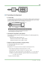
(1) CT orientation
×
○
Power monitor terminal
Current input
Voltage input
Check the installation for other phase and wiring schemes as well.
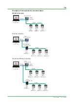
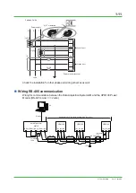
Wiring RS-485 communication
Wiring for communication between the Data Acquisition System GM and the UPM100 Power
Monitor (RS-485 4 wire <=> 2 wire)
(FG)
Approximately 1.2 km maximum length (up to 31 units)
Ethernet
RS-485
S GM
(RDA-) (RDB+) (SDA-) (SDB+) (SG)
(A-) (B+) (SG)
(A-) (B+) (SG)
(A-) (B+) (SG)
RS-485
RS-485
UPM100
GM10
UPM100
UPM100
Terminator
120Ω
Terminator
120Ω
PC

