IM 5E1E70-01E
11
WARNING
To prevent electrical shock, the controller should be mounted on the panel so that you do not accidentally
touch the terminals when power is being applied.
NOTE
The controller is shipped with the parameters set at the factory-set defaults. Check the default values
against the “Parameter List” in the following page (
P.15 to 17
), and change the parameter settings that need
to be changed.
The following section explains how to set and register parameter values.
There are no setup displays for parameters specific to functions, such as the optional digital input functions or
communication functions, if they were not selected at ordering.
The setting of some parameters (such as the control mode parameter CTL) determines whether the other param-
eters are displayed or not.
The flowchart (P.XXXXX) will help you understand how this works.
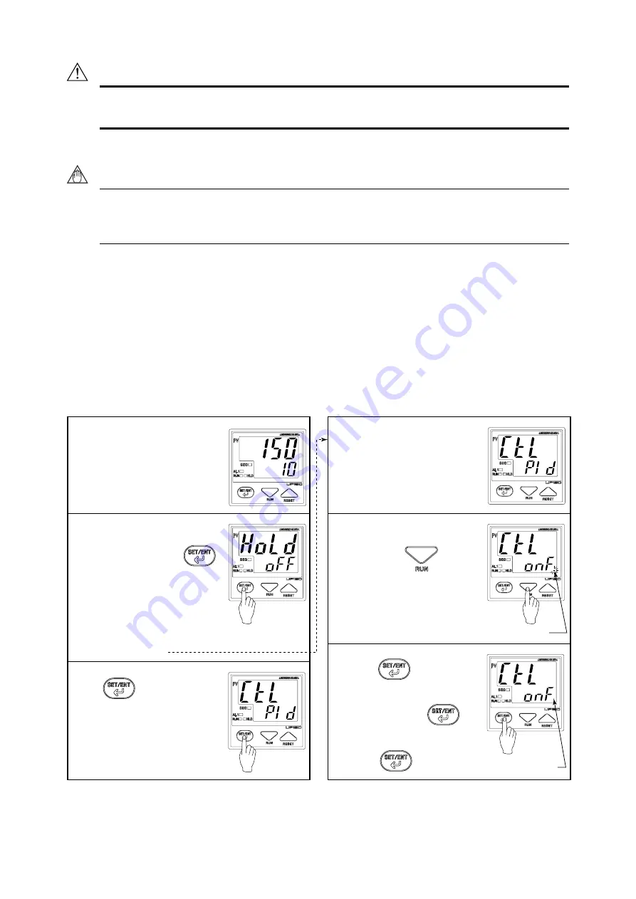
Step 1:
Confirm that the controller shows
the operation display
➀
,
➁
or
➂
.
Step 2:
To enter the Operating parameter
setting display, press the
key for at least 3 seconds.
• When UP150 is in Program
operation, the HOLD appears in
the display.
• When UP150 is not in Program
operation, the CTL appears. If
then, go to Step 4.
Step 3:
Press key twice to
display the CTL.
Step 4:
Confirm the control mode by the
display.
In this example, PID control mode
is selected.
Step 5:
When On/off control mode is
required, press key to
change control mode to On/off.
■
Changing Control Mode (CTL)
The period flashes.
Step 6:
Press the key once to
register the setting.
Control mode is now changed.
Another press of the key
calls up the “HYS” display. To
return to the operation display
➀
,
press the key for at least
3 seconds.
The period goes out.


