<Toc>
<6. Parameters>
6-13
IM 05E01D02-41E
1st Edition : May 31,2000-00
<Controller Settings>
•
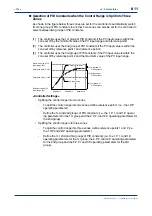
Splitting the control range into two zones
-
To split the control range into two zones, define reference point 1 (i.e., the 1.RP
operating parameter).
-
Define the 1st and 2nd groups of PID constants (i.e., the 1.P, 1.I and 1.D operat
ing parameters for the 1st group and the 2.P, 2.I and 2.D operating parameters for
the 2nd group).
-
Define the reference deviation (i.e., the RDV operating parameter).
TIP
The RDV parameter appears after the 4th group of PID parameters.
•
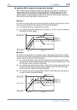
Splitting the control range into three zones
-
To split the control range into three zones, define reference points 1 and 2 (i.e.,
the 1.RP and 2.RP operating parameters).
-
Define the 1st, 2nd and 3rd groups of PID constants (i.e., the 1.P, 1.I and 1.D
operating parameters for the 1st group, the 2.P, 2.I and 2.D operating parameters
for the 2nd group and the 3.P, 3.I and 3.D operating parameters for the 3rd
group).
-
Define the reference deviation (i.e., the RDV operating parameter).
TIP
The RDV parameter appears after the 4th group of PID parameters.
●
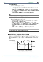
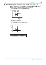
Hysteresis for PID switching (if Zone PID is used)
Hysteresis is set for PID switching at reference point 1, as shown in the figure below. The
hysteresis bandwidth is fixed at 0.5% of the span of the PV input range. Reference point 2
behaves in the same way as reference point 1, though the figure shows reference point 1
only.
2nd group of
PID constants
Reference point 1 (1.RP)
1st group of
PID constants
PV input value
2nd group of
PID constants
1st group of
PID constants
Hysteresis bandwidth
0.5% of PV input range span
1st group of
PID constants
2nd group of
PID constants
Summary of Contents for UP350
Page 2: ...Blank Page ...
Page 52: ...Blank Page ...
Page 62: ...Blank Page ...
Page 72: ...Blank Page ...
Page 94: ...Blank Page ...
Page 96: ...Blank Page ...


