background image

Technical
Information

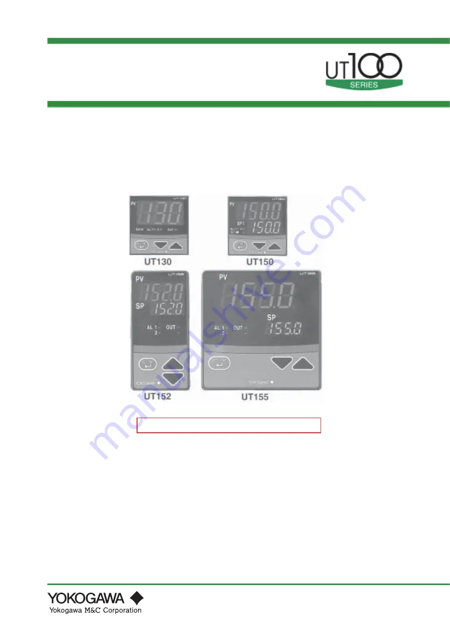
UT130, UT150/UT152/UT155
Temperature Controller

TI 05C01E02-01E

TI 05C01E02-01E

© Copyright Oct. 2001

1st Edition: Oct. 2001

Compact Body
Large Display
48 x 48mm

Compact Body
Full Functions
48 x 48mm

Simple Operation
Less Space
48 x 96mm

Simple Operation
Large Display
96 x 96mm

Easy-to-use Controllers for Operators

Features

• Large display
• Simple operation
• Available 24V AC/DC power supply
• Dynamic Auto Tune control
• Full alarm functions
• Retransmission outputs
•Timer function
• RUN / STOP switching

 The following product was discontinued as of November 30, 2015.  
 Discontinued product: UT152, UT155 Temperature Controller 

Summary of Contents for UT130

Page 1: ...mm Simple Operation Less Space 48 x 96mm Simple Operation Large Display 96 x 96mm Easy to use Controllers for Operators Features Large display Simple operation Available 24V AC DC power supply Dynamic Auto Tune control Full alarm functions Retransmission outputs Timer function RUN STOP switching The following product was discontinued as of November 30 2015 Discontinued product UT152 UT155 Temperat...

Page 2: ...Blank Page ...

Page 3: ...lo wchartandParameterListsofUT 100Seriescontr oller s Chapter4 Thisc haptere xplainsthebasicoperatingpr ocedureswhenusingaUT100 Seriescontr olleratfir st Chapter5 Thisc haptere xplainstheappliedoperationsnotdescribedinChapter4 Chapter6 Thisc haptere xplainsthebasicfunctionsofUT100Seriescontr oller s Chapter7 Thisc haptere xplainsatr oubleshootingf orerr orsbefore duringoperation Chapter8 Thisc hap...

Page 4: ...Blank Page ...

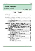
Page 5: ...d Description 3 2 3 3 UT150 UT152 UT155Names and Functions of Each Part Principles of Key Operation 3 6 3 4 UT150 UT152 UT155 Parameter Flowchart and Description 3 8 4 BASIC OPERATIONS 4 1 4 1 Setting Measured InputType and Scale Setting First 4 1 4 2 Setting Control Action 4 5 4 2 1 Selecting a Control Mode Dynamic Auto Tune Control PID Control ON OFF Control 4 5 4 2 2 Switching Direct Reverse Ac...

Page 6: ...9 6 DESCRIPTION OF EACH FUNCTION 6 1 6 1 ON OFF Control 6 1 6 1 1 ON OFF Control and Hysteresis 6 1 6 1 2 ON OFF Control Application Example 6 1 6 2 Proportional P Action 6 2 6 2 1 Differences between ON OFF Action and Proportional Action 6 2 6 2 2 Proportional Band P Details 6 2 6 2 3 Tuning the Proportional Band 6 3 6 3 Integral I Action 6 4 6 3 1 Integral Time I 6 4 6 3 2 Tuning the Integral Ti...

Page 7: ...E02 01E 1st Edition Oct 31 2001 00 7 TROUBLESHOOTING 8 1 8 INSTALLATION AND HARDWARE SPECIFICATIONS 8 1 8 1 Installation 8 1 8 2 Panel Cutout Dimensions and External Dimensions 8 3 8 3 Wiring 8 7 8 4 Hardware Specifications 8 12 ...

Page 8: ...Blank Page ...

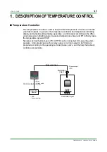
Page 9: ...rding to the differ ence between a indicating value measured temperature value and SP to finally make the temperature agree with SP Sensors such as thermocouple TC or RTD can be connected for measuring a tem perature And output types such as relay output or current output 4 to 20mA are prepared according to the operating terminal heater valve and the like that actually controls a temperature Heate...

Page 10: ...actions On the other hand the derivative action D action is the action that changes the output in proportion to the rate of change of deviation Since the output of derivative action depends on not the amount of deviation but its rate of change the larger the rate of change is the more intensive corrective action the controller takes to correct the pro cess response in advance Setting each optimum ...

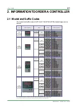
Page 11: ...ltage pulse output Current output Relay output Voltage pulse output Current output UT155 RN UT155 VN UT155 AN UT155 RN AL UT155 VN AL UT155 AN AL UT155 RN AL RET UT155 VN AL RET UT155 AN AL RET UT155 RN AL EX UT155 VN AL EX UT155 AN AL EX UT155 RN AL RS UT155 VN AL RS UT155 AN AL RS UT155 RN AL RET EX UT155 VN AL RET EX UT155 AN AL RET EX Relay output Voltage pulse output Current output Relay outp...

Page 12: ...ime proportional PID control 4 to 20mA output current PID Note1 Fixed N Fixed Option AL HBA EX RET RS V24 Alarm outputs 2 points Note2 Heater disconnection alarm includes the function of AL option Notes 2 and 3 SP1 SP2 switching starting of timer and RUN STOP switching byexternal contacts Notes 4 and 5 PV retransmission output in 4 to 20mA Note 3 Communication function Notes 4 and 6 Power Supply 2...

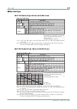
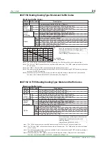
Page 13: ...ions User s Manual IM 05C01E12 10E separately See Page 2 8 Temperature controller 48 x 96 x 100mm Check the package contents against the list below Temperature controller of ordered model 1 Mounting bracket 1 User s Manual IM 05C01E12 01E 1 Heating CoolingType UT130 Heating CoolingType Model and Suffix Codes Model Model and Suffix Codes Suffix codes Description UT130 Temperature controller 48 x 48...

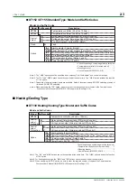
Page 14: ...A A A A A A N A N A N A N A N A N A N A AL HBA EX RS V24 R V A Check the package contents against the list below Temperature controller of ordered model 1 Mounting bracket 1 User s Manual IM 05C01E12 01E 1 A Available N A Not available UT152 UT155 Heating CoolingType Model and Suffix Codes Model Model and Suffix Codes Suffix codes Description UT155 Temperature controller 96 x 96 x 100mm UT152 Temp...

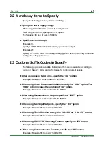
Page 15: ... available according to the model See 2 1 Model and Suffix Codes for combinations of options When using one or two Alarms specify the AL option Example Model and Suffix Codes UT130 RN AL When using Heater Disconnection Alarm specify the HBA option The HBA option includes the function of AL option Example Model and Suffix Codes UT150 RN HBA When using Retransmission Output specify the RET option Ex...

Page 16: ...ure controllers UT150 UT152 UT155 receive it after converting to a 1 to 5V DC signal Model Description X010 250 2 Resistor with M3 5 crimp on terminal lugs 12 13 Note Connecting a 250 resistor to the terminals is optional Model X010 250 2 resistor with M3 5 crimp on terminal lugs When receiving 4 20mA DC current signals set the PV input type to 1 5V DC range code 22 Receiving 4 20mA DC Current Sig...

Page 17: ...erature controller can be specified on ordering Items to specify Description Measured input type Specify 1 to 7 12 13 and 15 to 19 for UT130 Specify 1 to 23 for UT150 UT152 UT155 If no input type is specified at the time of ordering the temperaturecontroller is shipped with the parameter set to OFF unidentified In this case set the input type on customer side See 4 1 Setting Measured Input Type an...

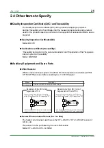
Page 18: ...their appearances When specifying the RS option be sure to order the required number of copies of Communication Functions User s Manual separately The following User s Manuals can be purchased separately User s Manual for UT130 A4 size Document Number IM05C01E02 41E User s Manual for UT150 UT152 UT155 A4 size Document Number IM05C01E12 41E Communication Functions User s Manual for UT130 UT150 UT15...

Page 19: ...t lamp lights up in orange during control output of standard type In heating cooling control the left lamp lights up in orange when the heating side output is active while the right lamp lights up in green when the cooling side output is active In the operating display it switches between the PV measured value and SP target setpoint displays Registers the data value changed using the data change k...

Page 20: ...press the key SP display lamp is on Note The data PV or SP selected in DSP is displayed at first Default PV display Dynamic Auto Tune PIDcontrol To Page 3 4 SP target setpoint can be changed in the operating display Refert to the Measured Input Ranges on Page 4 1 Displayed only for the AL or HBA option Not displayed when AL1 AL2 OFF Not displayed when AL1 AL2 21 or 22 Press the key for at least 3 ...

Page 21: ...L PV input filter OFF 0 1 to 120 seconds OFF 0 BS PV input bias 100 to 100 of measured input range span 0 of measured input range span LOC Key lock 0 No key lock 1 Prevents operations from being changed except for the changing of SP in the operating display 2 Prevents all parameter changing operations 1 Set 1 to enter the setup parameter setting display But if LOC 1 or 2 is already set the paramet...

Page 22: ...opriate values SPH SPL SC DR DSP Setup parameter setting display IN AL1 AL2 HY1 HY2 Displayed for the AL or HBA option PSL ADR BPS PRI STP DLN Displayed for the RS option Not displayed when CTL ONF on off control Not displayed for heating cooling type From Page 3 2 To Page 3 2 Note If no key is pressed for a period of 2 minutes or more while in the operating or setup parameter setting display the ...

Page 23: ...the SUPER function OFF 0 Does not use SUPER function Note Not displayed when on off control OFF 0 DR Direct reverse action 0 Reverse action 1 Direct action Note Not displayed for heating cooling type 0 DSP Priority of PV SP display 0 Displays PV 1 Displays target setpoint SP 0 ADR Controller address 1 to 99 However the number of controllers that can be connected per host device is 31 at the maximu...

Page 24: ...d the parameter values Pressing the key decreases the data value and pressing the key increases it Holding down the key will gradually increase the speed of the change PV display red Indicates PV measured value and character information such as parameter codes and error codes SP display green Indicates SP target setpoint and parameter values Alarm 1 AL1 Alarm 2 AL2 lamps red AL1 Lit when the alarm...

Page 25: ...l output of standard type In heating cooling control the upper lamp lights up in orange when the heating side output is active while the lower lamp lights up in green when the cooling side output is active Data change keys SET ENT key data registering key Registers the data value changed using the data change keys Switches between operating displays or parameter setting displays sequentially Press...

Page 26: ...PV value is displayed on PV display alternately N O T E When LOC 1 transfers to the setup parameter setting display To Page 3 10 SP1 or SP2 value can be changed at operating display1 SP2 is displayed when the lamp is flashing Timer 1 T1 operating display is shown when AL1 23 or 24 with the AL and EX options The value is the remaining time Timer 2 T2 operating display is shown when AL2 23 or 24 wit...

Page 27: ...C Heater disconnection current measured value HC is not a parameter to be set The current value 0 to 80 of heater disconnection detector is displayed Unit A ampere Settings When the display value is the heater current is not being measured A1 Alarm 1 setpoint PV alarm Unit C F Setting range minimum value to maximum value of measured input range scale Deviation alarm Unit C F Setting range 100 to 1...

Page 28: ...en DC voltage input range code is set AL1 AL2 HY1 HY2 Displayed for the AL or HBA option PSL ADR BPS PRI STP DLN Displayed for the RS option SC DR Not displayed when CTL ONF on off control Not displayed for heating cooling type DIS EOT Displayed for the EX option RTH RTL Displayed for the RET option TTU Displayed for the AL EX of HBA EX option B Note If no key is pressed for a period of 2 minutes ...

Page 29: ...l OFF 0 DR Direct reverse action 0 Reverse action 1 Direct action Note Not displayed for heating cooling type 0 ADR C o n t r o l l e r address 1 to 99 However the number of controllers that can be connected per host device is 31 at the maximum 1 BPS Baud rate 2 4 0 2400 bps 4 8 1 4800 bps 9 6 2 9600 bps 9 6 2 PRI Parity NON 0 Disabled EVN 1 Even parity ODD 2 Odd parity EVN 1 STP Stop bit 1 or 2 b...

Page 30: ...Blank Page ...

Page 31: ...ge F Rangecode C Rangecode F Unspecified OFF Unspecified OFF 1 2 3 4 5 6 7 12 13 15 16 17 18 19 31 32 33 34 35 36 37 42 43 45 46 47 48 Thermocouple RTD K J T E L U Pt100 JPt100 199 to 999 C 0 to 600 C 0 to 400 C 199 to 200 C 199 to 999 C 199 to 400 C 199 to 999 C 199 to 900 C 199 to 400 C 199 to 850 C 0 to 400 C 199 to 200 C 19 9 to 99 9 C 199 to 500 C 199 to 999 F 32 to 999 F 32 to 750 F 199 to 4...

Page 32: ...ple UT150 UT152 UT155 Display example Flashes during change Step 3 Press the or key to set the required setpoint for the measured input type The measured input type is set using a range code See Page 4 1 The period flashes while the value is being changed In this example K type thermocouple 0 0 to 400 0 C is set for the measured input type Step 4 Press the key once to register the setpoint The ope...

Page 33: ...t type To the next page Step 4 Press the key for 3 seconds or more to display the parameter A1 The parameter A1 appears only for the controller with the AL or HBA option The parameter CTL appears for the controller without the AL or HBA option Step 3 Press the key once to register the setpoint The operating display appears automatically The Step 4 onwards describes the procedure to set a display s...

Page 34: ...ed input scale The factory set default 100 0 appears on SP display From the previous page Step 11 Press the key once to register the setpoint The period is lit when the registration is completed Step 12 Press the key once to display the parameter RL minimum value of measured input scale The factory set default 0 0 is displayed on SP display In this example 0 0 is set for the minimum value of measu...

Page 35: ...ction are as follows ON OFF control ONF PID control PID Dynamic Auto Tune control SLF The period flashes while the value is being changed In this example the control mode is changed from Dynamic Auto Tune control setpoint SLF to PID control setpoint PID Step 6 Press the key once to register the setpoint Step 3 Press the key several times to display the parameter CTL control mode Flashes during cha...

Page 36: ...s greater 4mA PV value 20mA Direct Action PV SP ON Increases The ON state time increases PV SP ON Increases The ON state time increases PV SP OFF Decreases The ON state time decreases SP value Output value Increase Decrease Minimum PV value is smaller Maximum PV value is greater 4mA 20mA PV value Step 1 Bring the operating display into view UT130 Display example UT150 UT152 UT155 Display example S...

Page 37: ...The period is OFF Step 11 Press the key for 3 seconds or more to return to the operating display Step 7 Press the key several times to display the parameter DR direct reverse switching Step 5 Press the key to display 1 Step 6 Press the key once Flashes during change Flashes during change From the previous page From the previous page Step 8 for UT130 only Press the or key once to display the setpoi...

Page 38: ...T130 Display example UT150 UT152 UT155 Display example Step 5 Press the or key to set the cycle time The period flashes while the value is being changed In this example the cycle time is changed to 40 Step 6 Press the key once to register the setpoint Step 3 Press the key several times to display the parameter CT Flashes during change Flashes during change The period is OFF The period is OFF Step ...

Page 39: ...or the target setpoint In this example 200 C is set for the target setpoint Step 4 Press the key once to register the setpoint The period goes out then the setting changing of target setpoint is completed Note 1 Measured input value PV or target setpoint SP appears in the operating display The action of SP display lamp shows the status of display 1 SP display lamp is OFF PV display operating displ...

Page 40: ...is set for the target setpoint Operating Procedure Setting Changing SP in Operating Parameter Setting Display for SP1 and SP2 SP can be set or changed in the operating parameter setting display only for the con troller with the EX option And the SP is switched using the external contact input Refer to 5 6 Using Two Target Setpoints Page 5 4 The following operating procedure describes an example of...

Page 41: ...play Step 7 Press the or key to set the target setpoint 2 SP 2 The period flashes while the value is being changed In this example 300 0 C is set for the target setpoint 2 Step 8 Press the key once to register the setpoint Step 6 Press the key several times to display the parameter SP 2 target setpoint 2 The parameter SP 2 appears only for the controller with the EX option Flashes during change Th...

Page 42: ...note Deviation high limit 9 19 See note De energized on PV high limit 4 14 See note Deviation low limit 10 20 See note 25 24 De energized on PV low limit Timer function De energized 23 Timer function 5 15 See note De energized on deviation high limit 21 The contact is closed at input burnout 22 FAIL output OFF Measured value Opn off Opn off Cls on Deviation setting Hysteresis Cls on Measured value...

Page 43: ...often and the relay chattering occurs Alarm 1 type AL1 PV high limit alarm Alarm 1 hysteresis HY1 5 C A1 Alarm 1 setpoint 100 C Alarm 1 type AL1 PV high limit alarm Alarm 1 hysteresis HY1 15 C A1 Alarm 1 setpoint 100 C Short relay life When HY1 15 C the alarm does not turn on and off too often and the relay chattering does not occur Open and Closed above show the status of relay output of external...

Page 44: ...hange the parameter value set LOC 0 at first for disabling key lock then set LOC 1 once again NOTE Step 5 Press the key to display 1 Step 6 Press the key once Flashes during change Flashes during change Step 2 Press the key for 3 seconds or more to display the parameter A1 The parameter A1 appears only for the controller with the AL or HBA option The parameter CTL appears for the controller withou...

Page 45: ...The period is OFF The period is ON From the previous page From the previous page Step 9 Press the or key to set the alarm type code In this example the deviation high and low limit setpoint 7 is set for the alarm 1 type Flashes during change Flashes during change Step 13 Press the or key to set the alarm 1 hysteresis In this example 5 C is set for the alarm 1 hysteresis Flashes during change Flash...

Page 46: ...lay example UT150 UT152 UT155 Display example Step 2 Press the key for 3 seconds or more to display the parameter A1 The parameter A1 appears only for the controller with the AL or HBA option The parameter CTL appears for the controller without the AL or HBA option and in this case the alarm function is not Step 4 Press the or key to display 10 Step 5 Press the key once to register the setpoint Fl...

Page 47: ...esent can be read in the parameter HC heater current measured value Heater current in normal state Detecting current error 5 1digit The setpoint for heater detecting current is 10 of the current value at normal state PV input Alarm 1 Heater disconnection detection 200V AC 10kW CT Heater Furnace 10000W 200V 50A T C Example 1 Using one heater of 200V AC 10kW SSR Control output Relay or Voltage pulse...

Page 48: ...Blank Page ...

Page 49: ...of the scale to be controlled Set the displayed value at the minimum value of input signal Measured input range Example of Voltage Input Measured input range 270 C 1370 C 270 C 1370 C Parameters to be set for temperature input 1 Measured input type IN Set according to a sensor The display scale cannot be changed Refer to the Measured Input Ranges Page 4 1 Example of Temperature Input Display scale...

Page 50: ...t Setpoint Range To stabilize operation or protect equipment it may be necessary not to allow use of the full setpoint operating range but rather to some narrower range In such cases the minimum value and maximum value of target setpoint can be set to restrict the setpoint to the range between those values The minimum value and maximum value of target setpoint are set using the parameters SPL mini...

Page 51: ...ange scale C or F DNR UPR Parameter Range 0 C or F hour 1 C or F minute TMU Time Time PV SP Temperature Temperature Temperature Time SP SP1 SP SP2 1 When SP is changed Old SP Specified ramp rate New SP SP change 3 When power is turned on or power has recovered Specified ramp rate 2 When SP No is switched Power on or MAN to AUTO switching Specified ramp rate SP1 SP2 switching 70 C min UPR 140 2 70 ...

Page 52: ...P switching SP1 to SP2 SP2 when DI ON SP switching SP2 to SP1 SP1 when DI OFF 5 7 Retransmission of Measured InputValue in Current Signal This function is available for UT150 UT152 UT155 with the RET option The retransmission output range is factory set to between the maximum and minimum values of measured input range scale The retransmission output range is changeable The retransmission output ra...

Page 53: ...is available for UT150 UT152 UT155 with the EX option RUN STOP is switched using the external contact inputs The external contact input terminals for RUN STOP switching are different according to the parameter DIS setting Refer to the table below Set 1 or 2 for the setup parameter DIS to switch RUN STOP The symbol STP and PV value appears alternately on PV display in STOP mode PLC contact The exte...

Page 54: ...U T1 T2 Parameter Range Timer function energized 23 Timer function de energized 24 AL1 AL2 Timer time unit 0 hour and minute 1 minute and second TTU Heater switch on Timer setting time 20 minutes External contact input TMR on Timer starts Time up 180 C Temperature Time For external contact output energized OFF For external contact output de energized OFF SP ON ON Timer function Energized External ...

Page 55: ... then set LOC 1 once again 0 No key lock 1 2 Set key lock refer to the left 1 Transfer to the setup parameter setting display LOC Parameter Range LOC 1 Operating display Operating parameter setting display Press the key for at least 3 seconds To operating display Press the key for at least 3 seconds To operating parameter setting display Setup parameter setting display Set the parameter LOC 1 to a...

Page 56: ...erating display from the parameter setting display by pressing the key for at least 3 seconds PV display SP display SP display lamp is on during SP display To switch between PV and SP display press the key Power on Parameter DSP 0 Parameter DSP 1 5 12 Performing Heating Cooling Control In heating cooling control the controller outputs the result of PID computation after splitting it into heating p...

Page 57: ...and P x COL COL 1 100 Heating cooling MV output 0 For example if you set COL 2 0 and the heating side output is 10 at a certain deviation SP PV then the cooling side output will be 20 when the cooling side also reaches that deviation reverse Heating side proportional band Parameter P proportional band Cooling side proportional band Parameter P x Parameter COL 5 13 Communicating with PC or PLC This...

Page 58: ...esponse from address 3 controller Send response OK to the host device after 100 is written to SP Send response OK to the host device after 160 is written to SP Send response OK to the host device after 50 is written to SP Personal computer PLC and etc Communication Protocol RS 485 Communication Interface Communication Hardware 2 wire RS 485 communication system Communication Protocol Specification...

Page 59: ...ation 2 9600 1 EVN 1 8 1 1 When 2 Ladder is selected it is fixed to 8 When 3 ASCII mode is selected for MODBUS communication in protocol selection the data length is fixed to 7 When 4 RTU mode is selected it is fixed to 8 B A Shield RSB RSA RSB RSA UT130 UT150 UT130 UT150 PC or PLC Grounding resistance of no greater than 100Ω Grounding resistance of no greater than 100Ω Terminating resistor 220Ω 1...

Page 60: ...Blank Page ...

Page 61: ...the hysteresis should be set wider to prevent relay chattering and for the service life of the relay 0 C F to the temperature corresponding to 100 of the measured input range scale span HYS Parameter Range ONF ON OFF control PID PID control SLF Dynamic Auto Tune control CTL ON 6 1 2 ON OFF Control Application Example An example on the left figure shows two step ON OFF control using ON OFF control ...

Page 62: ...e operating principle SP Offset Smooth control performance SP 6 2 2 Proportional Band P Details Proportional band is defined as the amount of change in input or deviation as a percent of span required to cause the control output to change from 0 to 100 Because a narrower proportional band gives greater output change for any given deviation it therefore also makes the control performance more susce...

Page 63: ... or to manually tune the proportional band Work from larger to smaller numbers wider to narrower If cycling appears that means that the proportional band is too narrow Proportional band tuning cannot cancel an offset PV Time SP P is too small P is moderate P is too large If P is too small oscillation will appear in the PV 1 C F to the temperature corresponding to 100 of measured input range scale ...

Page 64: ...al action is not to be used the integral parameter is set to OFF Integral time I UT130 1 to 999 sec or OFF UT150 UT152 UT155 1 to 3600 sec or OFF I Parameter Range P 100 Ouptut P 100 e T 1 I 兰edt e Deviation TI Integral time Deviation Small integral time Large integral time Output On time ratio Output change due to I action Output change due to P action Integral time Time 6 3 2 Tuning the Integral...

Page 65: ...hange due to proportional action Derivative time D P 100 Output P 100 e e TD e Deviation TD Integral time Deviation Deviation Output On time ratio Output change due to P action Output change due to D action Derivative time Time dt d Large derivative time Small derivative time 6 4 2 Tuning the DerivativeTime The longer the derivative time is set the stronger the corrective action is and the more li...

Page 66: ...e Control is effective in the following cases PID computation at startup PID computation at disturbance T Temperature Time AMP SP 1 When the output travels up to 100 or down to 0 and remains there at power on 2 When the output travels up to 100 or down to 0 and remains there after changing a setpoint 3 When the process begins oscillating by disturbance and the like Parameter Range ONF ON OFF contr...

Page 67: ... I 兰edt PV TD dt d e Deviation TI Integral time TD Derivative time P Proportional band PV Measured input value 6 5 3 PID Auto Tuning The temperature controller automatically measures the process characteristics and sets PID constants which are control parameters to optimum values for the setpoint Auto tuning can be executed using simple key operations When auto tuning starts the temperature contro...

Page 68: ...00 0 50 0 ON OFF ON OFF T C 6 6 2 CycleTime This function is available in time proportional control Cycle time is the basic cycle period for a signal full cycle of ON OFF operation for a relay or voltage pulse output Reducing cycle time results in faster cycling and finer control In general setting about one tenth of the time constant of control object is standard For relay output 20 seconds or mo...

Page 69: ...putation value This output type is used to drive final control elements such as thyristors electro pneumatic converter pneumatic control valve combinations and electrical positioner motor driven valve or control motors combinations Output circuit Isolated from measured input Not isolated from heating and cooling sides nor from retransmission outputs Load resistance 600 or less Output accuracy 0 3 ...

Page 70: ...ation Diagram SUPER is effective in the following cases Overshoot must be suppressed Rise up time needs to be shortened Load varies often SP is changed frequently The SUPER function is effective when used together with the Auto Tune AT function 6 7 2 Effects of SUPER If the optimum PID values are being used then use of the SUPER function yields stable control without overshoot even on setpoint cha...

Page 71: ...to soak transition overshoot suppression control Process Small electric furnace P 1 8 I 317 sec D 79 sec from auto tuning SUPER effects 2 Temperature Time Temperature Time Without SUPER With SUPER The SUPER function is extremely effective for improving response to disturbances The overshoot experienced with conventional PID control in correction for disturbances is significantly reduced and settli...

Page 72: ...Blank Page ...
Page 73: ...during Operation 1 If the controller displays one of the following carry out the appropriate remedy for the particularerror Display Error content Remedy P Er Flashing period on PV display The parameter is abnormal Check the settings of all the parameters and set them at their proper values B o Input burnout Check the sensor wiring and correct it OOO PV over scale PV exceeds its effective range Che...

Page 74: ... no effect on the controller operation i e normal operation continues For power failures longer than 20ms or longer than 1ms when V24 is specified however the status will be as follows The controller action at power recovery is the same as at power on Alarm action Continues but alarms with a waiting action enter the waiting state once Setting parameters Maintained Auto tuning Canceled ...

Page 75: ... element etc is protected from wind 4 The temperature can be maintained at about 8 There is no splashing of water and 23 C with minimal fluctuation 9 There are no flammable materials 5 There is no direct heat radiation Never place the controller directly on flammable items If the controller has to be installed close to flammable items or equipment be sure to enclose the controller in shielding pan...

Page 76: ... part numbers T9115YE and T9115YD are available for the UT152 and UT155 controllers respectively How to Mount UT130 UT150 1 Affix the bracket over the back end of the controller 2 Push the bracket to the panel and then secure the bracket into position Panel Bracket UT130 UT150 How to remove the bracket To move the bracket push down the center of the upper and lower parts of the controller softly T...

Page 77: ...s UT130 Panel cutout dimensions and external dimensions max 61 Panel thickness max 47 8 max 44 8 max 44 8 100 12 48 48 1 to 10 Unit mm 1 General Mounting min 70 min 70 45 0 6 0 45 0 6 0 25 25 N 1 x48 45 0 6 0 0 6 0 45 2 Side by side Close Mounting Splash proof construction is unavailable IP65 is unavailable ...

Page 78: ...1 Panel thickness max 44 8 max 44 8 max 44 8 100 12 1 to 10 Unit mm 1 General Mounting min 70 min 70 45 0 6 0 45 0 6 0 25 25 N 1 x48 45 0 6 0 0 6 0 45 2 Side by side Close Mounting N is the number of controllers If N 5 then measure the actual length 48 48 Splash proof construction is unavailable IP65 is unavailable ...

Page 79: ... General Mounting 2 Side by side Close Mounting min 70 min 145 92 0 8 0 45 0 6 0 25 53 N 1 x48 45 0 6 0 0 8 0 92 N is the number of controllers If N 5 then measure the actual length 1 1021 301 20 48 max 44 6 max 91 8 max 112 100 96 Panel thickness 1 to 10 11 Splash proof construction is unavailable IP65 is unavailable ...

Page 80: ... Mounting 2 Side by side Close Mounting min 117 min 145 92 0 8 0 92 0 8 0 25 53 N 1 x96 92 0 8 0 0 8 0 92 N is the number of controllers If N 5 then measure the actual length max 91 8 96 1 1051 6041 5031 4021 3011 20 96 11 100 max 91 8 max 112 Panel thickness 1 to 10 Splash proof construction is unavailable IP65 is unavailable ...

Page 81: ... to de energize the controller 2 For thermocouple input use shielded compensating lead wires For RTD input use shielded wires which have low resistance and no resistance difference between the 3 wires See the table given later for the specifications of the cables and terminals and the recommended products 3 The control output relay cannot be replaced even though it has a limited service life 100 0...

Page 82: ...l Arrangement StandardType 1 2 3 4 5 6 7 8 9 10 11 12 13 14 15 TC Input RTD Input Measured Value PV Input Universal input selectable input type 7 8 6 7 8 B b A RS 485 3 4 5 ALM2 ALM1 COM RSB RSA SG Alarm Outputs When AL or HBA is specified When HBA is specified When RS is specified Heater Current Detection Input 1 2 11 12 13 NO COM Relay Contact Output Voltage Pulse Output Control Output Specify o...

Page 83: ...e defined as terminals and for a standard type and as terminals and for a heating cooling type 1 2 3 4 NOTE The and stand for the polarityfor DC 24V power supply UT152 155Terminal Arrangement StandardType Note The terminal arrangements of the UT152 and UT155 are the same 11 21 22 23 24 25 26 27 28 29 30 12 13 14 15 16 17 18 19 20 TC Input DC mV or V Input RTD Input Measured Value PV Input 12 13 12...

Page 84: ... 13 14 15 TC Input DC mV or V Input RTD Input Measured Value PV Input 7 8 7 8 6 7 8 B b A ALM2 ALM1 COM Alarm Outputs When AL or HBA is specified RS 485 3 4 5 RSB RSA SG When RS is specified 11 12 13 NO COM Relay Contact Output 4 to 20 mA DC Output Voltage Pulse Output Heating side Control Output Specify one for the output signal type 14 15 14 15 14 15 NO COM Specify one for the output signal type...

Page 85: ...utput 29 30 29 30 29 30 Heater Current Detection Input 24 25 CT When AL or HBA is specified ALM2 ALM1 COM Alarm Outputs 16 17 18 Note The terminal arrangements of the UT152 and UT155 are the same NO COM NO COM To prevent damage to the controller never provide 100 240V AC power supply for power supply AC DC 24V model when V24 is specified CAUTION External Contact Inputs 21 22 23 SP2 STOP TMR STOP C...

Page 86: ...t period vibrations 14 7m s2 1 5G for 15 seconds or less Shock 98m s2 10G for 11 milliseconds or less Mounting angle Upward incline of up to 30 degrees downward incline is not allowed Altitude 2000m or less above sea level Maximum Effects from Operating Conditions 1 Temperature effects Thermocouple DC mV and DC V input 2 V C or 0 02 of F S C whichever is larger Resistance temperature detector 0 05...

Reviews: