
<Toc> <Ind>
3-9
TI 05C01E02-01E
1st Edition : Oct. 31, 2001-00
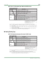
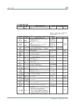
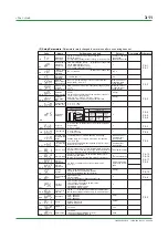
CTL
Control mode
ONF(0): On/off control
PID(1): PID control
SLF(2): Dynamic auto tune control (cannot be set for heating/cooling control)
SLF(2) :for standard type;
PID(1) : for
heating/cooling type
AT
Auto-tuning
OFF(0): Stop auto-tuning
ON(1): Start auto-tuning
OFF(0)
P
Proportional
band
1
°
C/
°
F
to the temperature that corresponds to 100% of
the measured input range (scale) span
5% of measured
input range (scale)
I
Integral time
1 to 3600 seconds;
OFF(0): no integral action
240 seconds
D
Derivative
time
1 to 3600 seconds;
OFF(0): no derivative action
60 seconds
MR
Manual reset
—100 to 100%
50.0% for standard type;
0.0% for heating/cooling type
COL
Cooling-side
gain
0.01 to 9.99 times
1.00 times
DB
Dead band
■
PID control Unit:
°
C/
°
F
Setting range: —(proportional band setting) to +(proportional band setting)
■
On/off control Unit:
°
C/
°
F
Setting range: —50 to +50% of measured input range (scale)span
0% of measured
input range (scale)
span
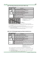
HYS
Hysteresis for
on/off control
0
°
C/
°
F
to the temperature that corresponds to 100% of
the measured input range (scale) span
0.5% of measured
input range (scale)
span
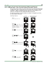
CT
Control
output
cycle time
1 to 240 seconds
30 seconds
CTC
Cooling-side
control output
cycle time
1 to 240 seconds
30 seconds
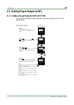
SP1
Target
setpoint 1
Minimum value (SPL) to maximum value (SPH) of target
setpoint range
Unit:
°
C/
°
F
There are also optional engineering units for voltage input.
SPL
SP2
Target
setpoint 2
SPL
FL
PV input filter
OFF(0), 1 to 120 seconds
OFF(0)
BS
PV input bias
—100 to 100% of measured input range (scale) span
0% of measured input
range (scale) span
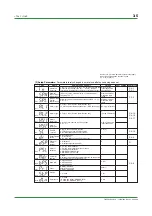
LOC
Key lock
0
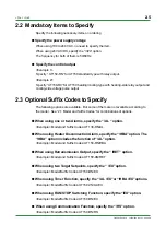
Code
Name
Setting range and unit
Default
User setting Reference page
Reference page
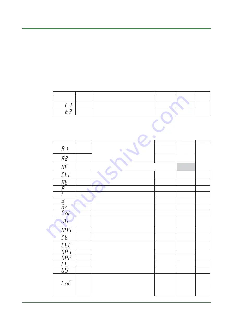
HC
Heater disconnection
current measured
value
HC is not a parameter to be set. The current value (0 to 80) of heater disconnection
detector is displayed. Unit: A (ampere)
Settings: When the display value is — — — —, the heater current is not being measured.
A1
Alarm 1
setpoint
■
PV alarm Unit:
°
C/
°
F
Setting range: minimum value to maximum value of measured input
range (scale)
■
Deviation alarm Unit:
°
C/
°
F
Setting range: —100 to 100% of measured input range (scale) span
■
Heater disconnection alarm Unit: A (ampere)
Setting range: OFF(0), 1 to 80 (can be set for the alarm 1 setpoint only)
Max. value of
measured input range
(scale) (PV alarm)
A2
Alarm 2
setpoint
Min. value of
measured input range
(scale) (PV alarm)
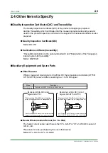
Code
Name
(SP value display)
Target
setpoint
Setting range and unit
Minimum value (SPL) to maximum value (SPH) of target setpoint
range
Default
User setting
SPL
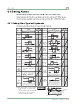
T1
Timer
setting 1
0.0 to 99.59
Unit: minutes and seconds or hours and minutes
Set the timer time unit using the parameter TTU.
For example, 15.25 sets 15 minutes and 25 seconds when
the unit is minutes and seconds.(T1 is for AL1, and T2 is for AL2)
0.00
T2
Timer
setting 2
0.00
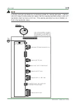
Numbers in ( ) are the parmeter setpoints that apply
when the communication function is used.
Ex. OFF(0), ON(1)
0: No key lock
1: Prevents operations from being changed except for the
changing of SP in the operating display
2: Prevents all parameter changing operations
—1: Set -1 to enter the setup parameter setting display.
But if LOC=1 or 2 is already set, the parameter value
can not be changed by setting LOC=-1 only. To
change the parameter value, set LOC=0 at first (for
disabling keylock), then set LOC=-1 once again.
P.4-10
P.5-6
P.4-12
P.4-16
P.4-17
P.4-5
P.6-1
P.6-6
P.6-7
P.6-2
P.6-4
P.6-5
P.6-4
P.5-8
P.5-8
P.6-1
P.4-8
P.6-8
P.6-8
P.4-10
P.5-4
P.5-2
P.5-1
P.5-7
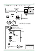
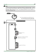
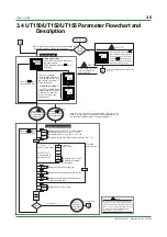
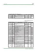
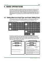
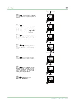
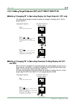
(1) Target Setpoint (SP) and Timer Settings 1 and 2
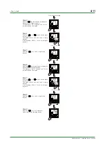
(2) Operating Parameters:
Parameters changed rather frequently during operation.
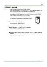
Summary of Contents for UT130
Page 2: ...Blank Page ...
Page 4: ...Blank Page ...
Page 8: ...Blank Page ...
Page 30: ...Blank Page ...
Page 48: ...Blank Page ...
Page 60: ...Blank Page ...
Page 72: ...Blank Page ...


