

<Toc> <Ind>
4-7
TI 05C01E02-01E
1st Edition : Oct. 31, 2001-00
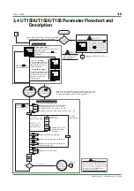
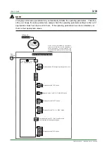
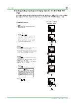
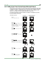
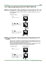
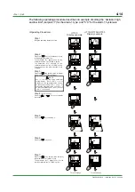
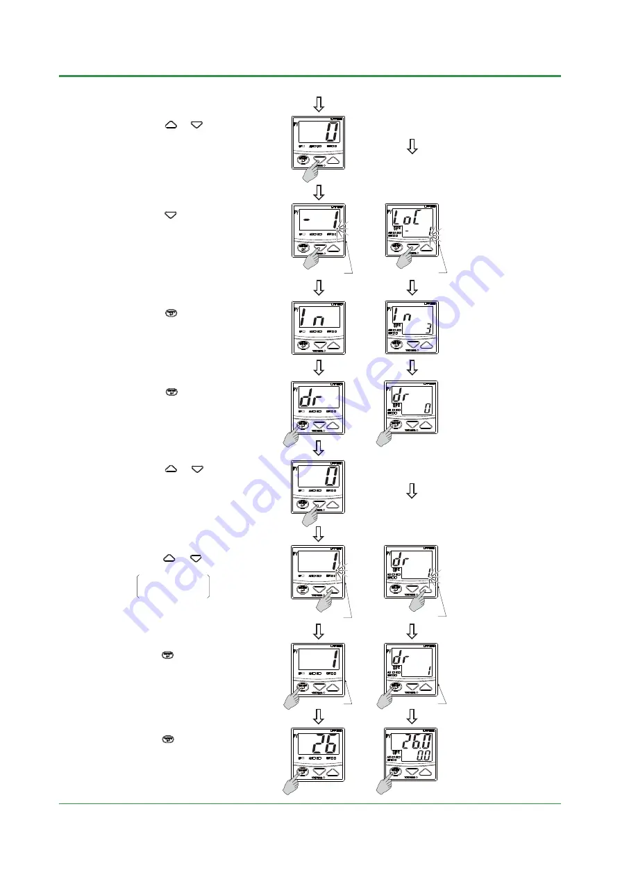
Step 9:
Press the or key to set the direct
action (setpoint: 1).
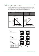
Reverse action: DR = 0
Direct action: DR = 1
Step 10:
Press the key once to register the setpoint.
Flashes during change.
Flashes during change.
The period is OFF.
The period is OFF.
Step 11:
Press the key for 3 seconds or more
to return to the operating display.
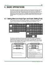
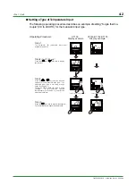
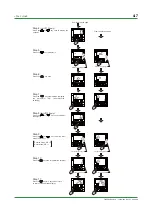
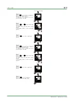
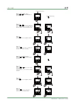
Step 7:
Press the key several times to display
the parameter "DR" (direct/reverse
switching).
Step 5:
Press the key to display "-1".
Step 6:
Press the key once.
Flashes during change.
Flashes during change.
From the previous page
From the previous page
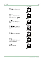
Step 8
(for UT130 only)
:
Press the or key once to display
the setpoint.
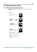
Step 4
(for UT130 only)
:
Press the or key once to display the
setpoint.
Summary of Contents for UT130
Page 2: ...Blank Page ...
Page 4: ...Blank Page ...
Page 8: ...Blank Page ...
Page 30: ...Blank Page ...
Page 48: ...Blank Page ...
Page 60: ...Blank Page ...
Page 72: ...Blank Page ...


