
<Toc> <Ind>
5-1
TI 05C01E02-01E
1st Edition : Oct. 31, 2001-00
5. APPLIED OPERATIONS
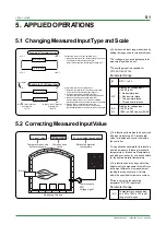
5.1 Changing Measured Input Type and Scale
•
The measured input range is decided by
setting the range code for measured input.
•
For voltage input, any display scale for
measured input can be set.
•
The voltage input is available for
UT150/UT152/UT155.
OFF, 1 to 23
IN
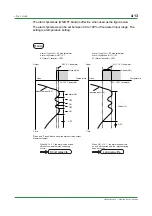
Parameter Range
Display for voltage input
(IN= 20 to 23)
0: No decimal place
1: One decimal place
2: Two decimal places
3: Three decimal places
DP
Display for voltage input
(IN= 20 to 23)
-1999 to 9999 However,RL<RH
RH
RL
Minimum value of measured
input scale (RL)
1V
5V
Input signal
0.0m
3
/h
50.0m
3
/h
Maximum value of measured
input scale (RH)
RL
RH
Parameters to be set for voltage input
1. Measured input type (IN): Set according to input signal.
Refer to the Measured Input Ranges (Page 4-1).
2. Decimal point position of measured input (DP):
Set the decimal point position of measured input display.
3. Maximum value of measured input scale (RH):
Set the maximum value of the scale to be controlled.
(Set the displayed value at the maximum value of input signal.)
4. Minimum value of measured input scale (RL):
Set the minimum value of the scale to be controlled.
(Set the displayed value at the minimum value of input signal.)
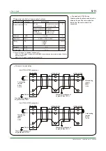
Measured input range
Example of Voltage Input
Measured input range
-270
°
C
1370
°
C
-270
°
C
1370
°
C
Parameters to be set for temperature input
1. Measured input type (IN): Set according to a sensor.
The display scale cannot be changed.
Refer to the Measured Input Ranges (Page 4-1).
Example of Temperature Input
Display scale
Measured input scale
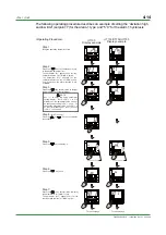
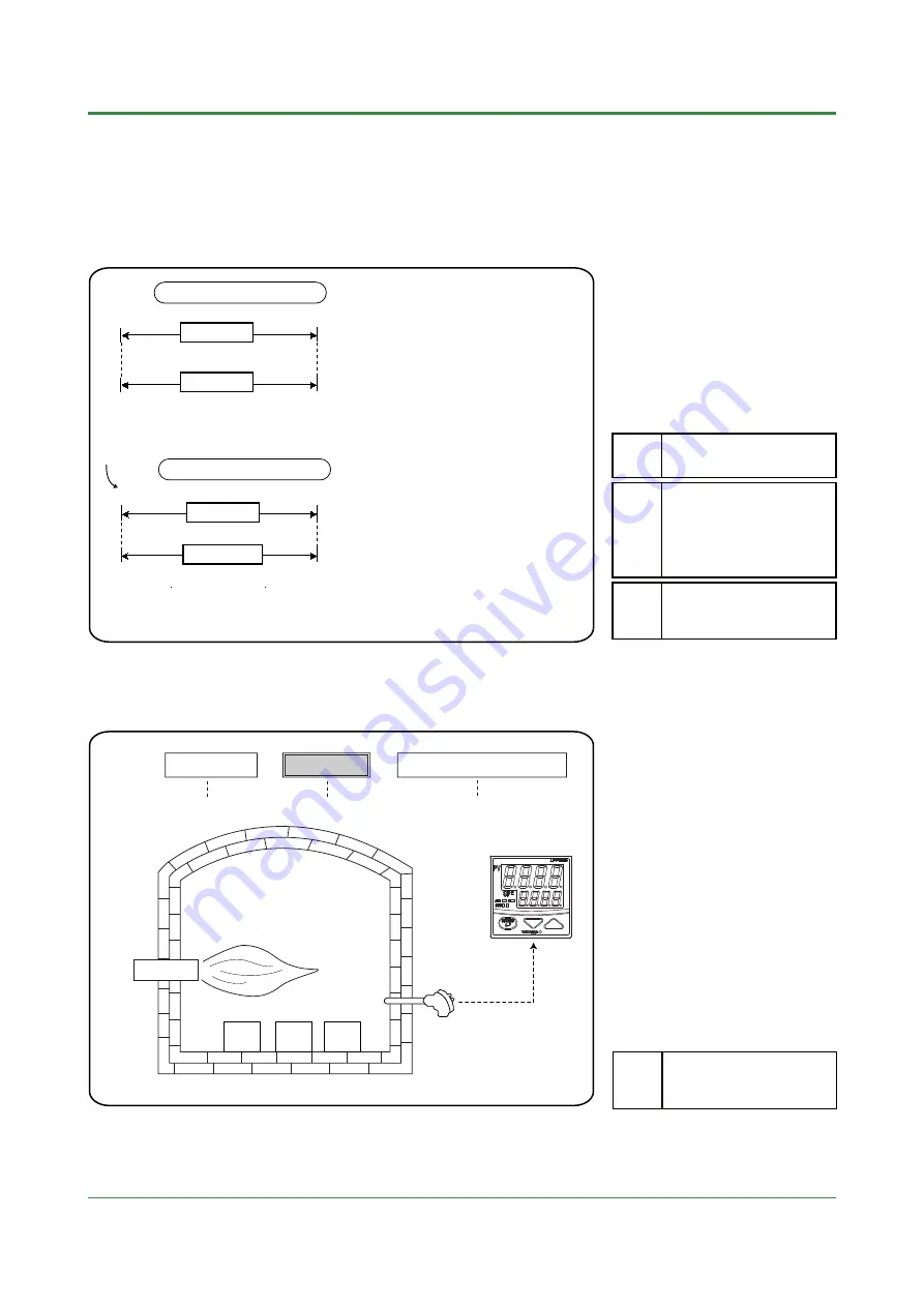
5.2 Correcting Measured Input Value
•
This function allows bias to be summed
with input to develop a PV (measured)
value for display and control use inside
the controller.
•
An application example for this function
would be measure furnace atmospheric
temperature or furnace wall temperature,
and add a correction for use as substitute
for the heated material temperature.
•
This function can also be used for fine
adjustment to compensate for small inter-
instrument differences in measurement
reading that can occur even if all are
within the specified instrument accuracy.
•
Bias is set using the operating
parameter "BS" (PV input bias ).
Parameter Range
Temperature corresponding
to -100 to 100% of PV input
range (scale) span
BS
PV input value +
PV input bias
PV value
inside the controller
+
Burner
Re-heating furnace
Temperature sensed
by thermocouple
Compensation
value
Thermocouple
RTD
Voltage signal
Estimated material
temperature
Summary of Contents for UT130
Page 2: ...Blank Page ...
Page 4: ...Blank Page ...
Page 8: ...Blank Page ...
Page 30: ...Blank Page ...
Page 48: ...Blank Page ...
Page 60: ...Blank Page ...
Page 72: ...Blank Page ...


