


5-10
<Toc> <Ind>
TI 05C01E02-01E
1st Edition : Oct. 31, 2001-00
•
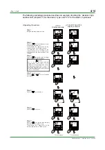
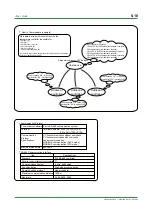
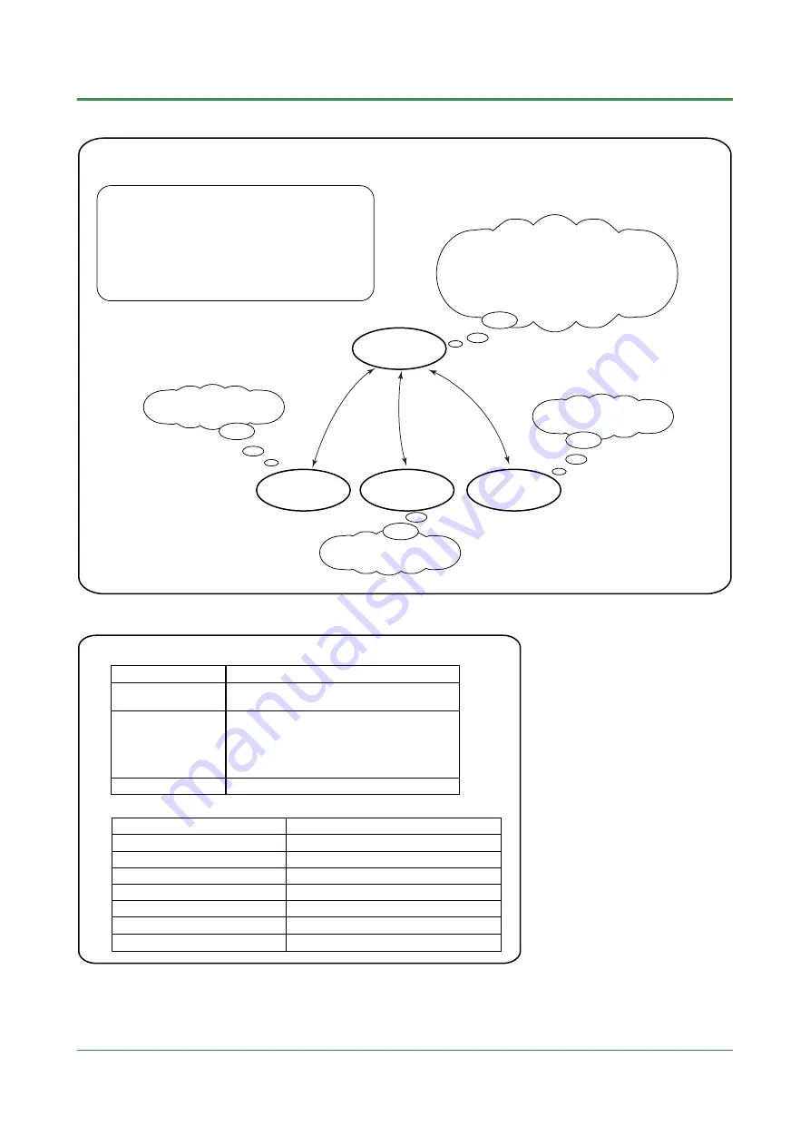
How to Communicate (example)
Host device
Main data that read (R)/write (W) from/to the
temperature controller is possible for:
•
PV input (R)
•
SP (R/W)
•
Control output value (R)
•
Error information (R)
•
Alarm condition (R)
•
Parameter setting value (R)
*For details, refer to the User’s Manual "UT100 Series Communication
Functions" (IM 05C01E12-10E).
Address-1
controller
Address-2
controller
Address-3
controller
The procedure for SP change
1. Write "100" to the SP parameter of address-1 controller.
2. Receive response from address-1 controller.
3. Write "50" to the SP parameter of address-2 controller.
4. Receive response from address-2 controller.
5. Write "160" to the SP parameter of address-3 controller.
6. Receive response from address-3 controller.
Send response "OK" to the host
device after "100" is written to SP.
Send response "OK" to the host
device after "160" is written to SP.
Send response "OK" to the host
device after "50" is written to SP.
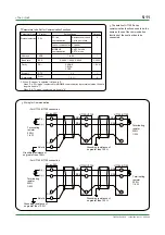
Personal computer, PLC and etc.
•
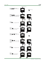
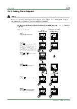
Communication Protocol
•
RS-485 Communication Interface
Communication Hardware 2-wire RS-485 communication system
Communication
Protocol
Specifications
PC link communication without sum check
PC link communication with sum check
Ladder communication
MODBUS communication (ASCII mode)
MODBUS communication (RTU mode)
Terminal
Maximum Baud Rate 9600 bps
Terminal numbers: 3 to 5 (UT130/UT150),
26 to 28 (UT152/UT155)
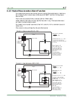
Item
Standard
EIA RS-485 compliant
Maximum number of devices to be connected 31
Communication System 2-wire, half duplex
Synchronization Start-stop synchronization
Communication protocol Non-procedural
Maximum communication distance 1200 m
Baud rate 2400, 4800, 9600
Specifications
Summary of Contents for UT130
Page 2: ...Blank Page ...
Page 4: ...Blank Page ...
Page 8: ...Blank Page ...
Page 30: ...Blank Page ...
Page 48: ...Blank Page ...
Page 60: ...Blank Page ...
Page 72: ...Blank Page ...


