
<Toc> <Ind>
8-9
TI 05C01E02-01E
1st Edition : Oct. 31, 2001-00
●
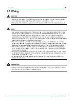
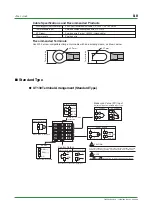
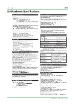
UT150 Terminal Arrangement (Standard Type)
1
2
3
4
5
6
7
8
9
10
11
12
13
14
15
TC Input
DC mV or V Input
RTD Input
Measured Value (PV) Input
Universal input-selectable input type
7
8
7
8
6
7
8
+
—
+
—
B
b
A
ALM2
ALM1
COM
Alarm Outputs
When /AL or /HBA
is specified.
When /HBA
is specified.
When /RET
is specified.
RS-485
3
4
5
RSB(+)
RSA(—)
SG
When /RS is specified.
Heater Current Detection Input
Retransmission Output
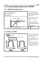
(Note 1)
1
2
11
12
13
+
—
1
2
CT
Relay Contact Output
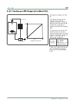
4 to 20 mA DC Output
Voltage Pulse Output
Control Output
Specify one for the output signal type.
14
15
14
15
+
—
14
15
+
—
NO
COM
External Contact Inputs
3
4
5
SP2
STOP
TMR
STOP
COM
When /EX is specified.
Parameter DIS
SP1/SP2
switching
SP2
when DI=ON
2
1
0 (Default)
TMR
STOP
SP2
STOP
RUN/STOP
switching
STOP
when DI=ON
RUN/STOP
switching
STOP
when DI=ON
SP1/SP2
switching
SP2
when DI=ON
Timer starts
when DI=ON
Timer stops
when DI=OFF
Timer starts
when DI=ON
Timer stops
when DI=OFF
9
L
N
10
Power Supply
9
10
AC/DC 24V
100-240V AC
When /V24
is specified.
+
—
To prevent damage to
the controller, never provide
100-240V AC power supply
for power supply AC/DC 24V
model (when /V24 is
specified).
CAUTION
Note 1: The heater current detection input terminals (option code: /HBA)
are defined as terminals and for a standard type and as
terminals and for a heating/cooling type.
1
2
3
4
NOTE
The and stand for the polarityfor DC 24V power supply.
+
—
●
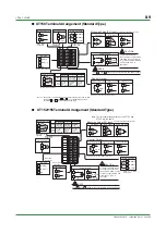
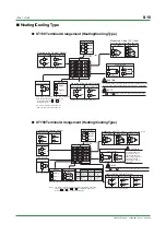
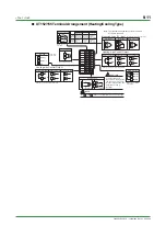
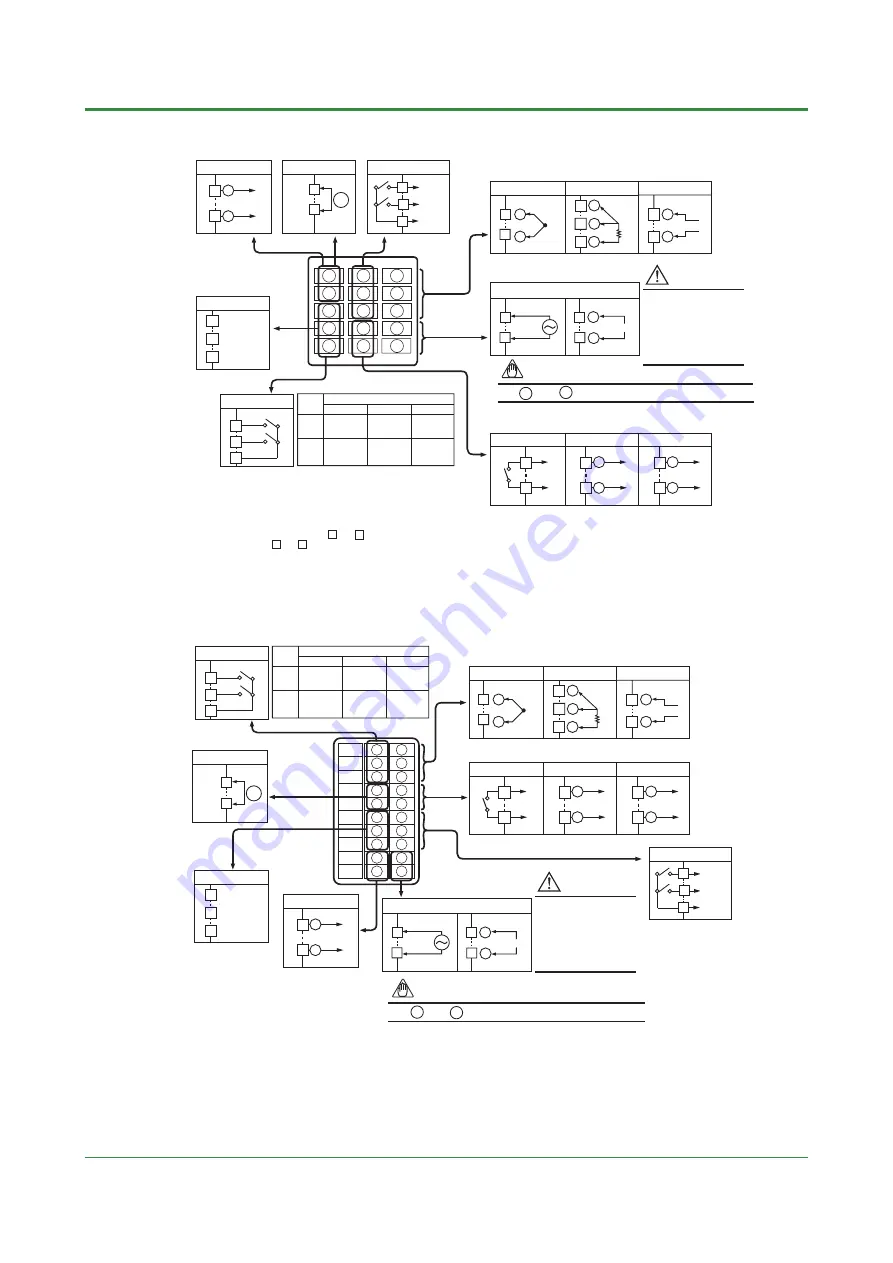
UT152/155 Terminal Arrangement (Standard Type)
Note: The terminal arrangements of the UT152 and
UT155 are the same.
11
21
22
23
24
25
26
27
28
29
30
12
13
14
15
16
17
18
19
20
TC Input
DC mV or V Input
RTD Input
Measured Value (PV) Input
12
13
12
13
11
12
13
+
—
+
—
B
b
A
RS-485
26
27
28
RSB(+)
RSA(—)
SG
When /RET
is specified.
Specify one for the output signal type.
When /RS
is specified.
Relay Contact Output
4 to 20 mA DC Output
Voltage Pulse Output
Control Output
14
15
14
15
+
—
14
15
+
—
Retransmission Output
+
—
29
30
When /HBA
is specified.
Heater Current Detection Input
24
25
CT
When /AL or /HBA
is specified.
ALM2
ALM1
COM
Alarm Outputs
16
17
18
NO
COM
To prevent damage to the
controller, never provide
100-240V AC power supply
for power supply AC/DC 24V
model (when /V24 is
specified).
CAUTION
External Contact Inputs
21
22
23
SP2
STOP
TMR
STOP
COM
When /EX is
specified.
Parameter DIS
SP1/SP2
switching
SP2
when DI=ON
2
1
0 (Default)
TMR
STOP
SP2
STOP
RUN/STOP
switching
STOP
when DI=ON
RUN/STOP
switching
STOP
when DI=ON
SP1/SP2
switching
SP2
when DI=ON
Timer starts
when DI=ON
Timer stops
when DI=OFF
Timer starts
when DI=ON
Timer stops
when DI=OFF
19
L
N
20
Power Supply
19
20
AC/DC 24V
100-240V AC
When /V24
is specified.
+
—
NOTE
The and stand for the polarityfor DC 24V power supply.
+
—
Universal input-selectable input type
Summary of Contents for UT130
Page 2: ...Blank Page ...
Page 4: ...Blank Page ...
Page 8: ...Blank Page ...
Page 30: ...Blank Page ...
Page 48: ...Blank Page ...
Page 60: ...Blank Page ...
Page 72: ...Blank Page ...


