
IM 05P08D31-11EN page 11/12
■
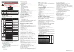
PV2 Input Setting Parameter
Menu symbol:
(PV2)
Parameter
symbol
Name of Parameter
Setting Range
Initial
value
User
setting
Display
level
(IN)
PV2 input type
K1: -270.0 to 1370.0
0
C / -450.0 to 2500.0
0
F
K2: -270.0 to 1000.0
0
C / -450.0 to 2300.0
0
F
K3: -200.0 to 500.0
0
C / -200.0 to 1000.0
0
F
J: -200.0 to 1200.0
0
C / -300.0 to 2300.0
0
F
T1: -270.0 to 400.0
0
C / -450.0 to 750.0
0
F
T2: 0.0 to 400.0
0
C / -200.0 to 750.0
0
F
B: 0.0 to 1800.0
0
C / 32 to 3300
0
F
S: 0.0 to 1700.0
0
C / 32 to 3100
0
F
R: 0.0 to 1700.0
0
C / 32 to 3100
0
F
N: -200.0 to 1300.0
0
C / -300.0 to 2400.0
0
F
E: -270.0 to 1000.0
0
C / -450.0 to 1800.0
0
F
L: -200.0 to 900.0
0
C / -300.0 to 1600.0
0
F
U1: -200.0 to 400.0
0
C / -300.0 to 750.0
0
F
U2: 0.0 to 400.0
0
C / -200.0 to 1000.0
0
F
W: 0.0 to 2300.0
0
C / 32 to 4200
0
F
PL2: 0.0 to 1390.0
0
C / 32.0 to 2500.0
0
F
P2040: 0.0 to 1900.0
0
C / 32 to 3400
0
F
WRE: 0.0 to 2000.0
0
C / 32 to 3600
0
F
JPT1: -200.0 to 500.0
0
C / -300.0 to 1000.0
0
F
JPT2: -150.0 to 150.0
0
C / -200.0 to 300.0
0
F
PT1: -200.0 to 850.0
0
C / -300.0 to 1560.0
0
F
PT2: -200.0 to 500.0
0
C / -300.0 to 1000.0
0
F
PT3: -150.00 to 150.00
0
C / -200.0 to 300.0
0
F
0.4-2V: 0.400 to 2.000 V
1-5V: 1.000 to 5.000 V
4-20: 4.00 to 20.00 mA
0-2V: 0.000 to 2.000 V
0-10V: 0.00 to 10.00 V
0-20 : 0.00 to 20.00 mA
-1020: -10.00 to 20.00 mV
0-100: 0.0 to 100.0 mV
0-10V
EASY
(UNIT)
PV2 input unit
-: No unit, C: Degree Celsius
-: No unit, - -: No unit, - - -: No unit,
F: Degree Fahrenheit
C
(RH)
Maximum value of PV2
input range
Depends on the input type.
- For temperature input -
Set the temperature range that is
actually controlled. (RL<RH)
- For voltage / current input -
Set the range of a voltage / current
signal that is applied.
The scale across which the voltage/
current signal is actually controlled
should be set using the maximum
value of input scale (SH) and mini-
mum value of input scale (SL).
(Input is always 0% when RL = RH.)
5.000
(RL)
Minimum value of PV2
input range
1.000
(SDP)
PV2 input scale decimal
point position
0: No decimal place
1: One decimal place
2: Two decimal places
3: Three decimal places
4: Four decimal places
2
(SH)
Maximum value of PV2
input scale
-19999 to 30000, (SL<SH),
| SH - SL | ≤ 30000
10000
(SL)
Minimum value of PV2
input scale
0
(BSL)
PV2 input burnout action
OFF: Disable
UP: Upscale
DOWN: Downscale
OFF
STD
(A.BS)
PV2 analog input bias
-100.0 to 100.0% of each input range
span (EUS)
0.0 % of
PV input
range
span
(A.FL)
PV2 analog input filter
OFF, 1 to 120 s
OFF
W: W-5% Re/W-26% Re(Hoskins Mfg.Co.). ASTM E988, WRE: W97Re3-W75Re25
■
Input Range, SP Limiter Setting Parameter
Menu symbol:
(MPV)
Parameter
symbol
Name of Parameter
Setting Range
Initial
value
User
setting
Display
level
(P.UNI)
Control PV input unit
-: No unit
C: Degree Celsius
-: No unit
- -: No unit
- - -: No unit
F: Degree Fahrenheit
Same
as PV
input
unit
(LP1)
STD
(LP2)
(P.DP)
Control PV input decimal
point position
0: No decimal place
1: One decimal place
2: Two decimal places
3: Three decimal places
4: Four decimal places
Depends
on the
input type
(LP1)
(LP2)
(P.RH)
Maximum value of
control PV input range
-19999 to 30000, (P.RL<P.RH),
| P.RH - P.RL | ≤ 30000
Depends
on the
input type
(LP1)
(LP2)
(P.RL)
Minimum value of control
PV input range
Depends
on the
input type
(LP1)
(LP2)
(SPH)
SP high limit
0.0 to 100.0% of PV input range (EU),
(SPL<SPH)
100.0 %
of PV
input
range
(LP1)
(LP2)
(SPL)
SP low limit
0.0 %
of PV
input
range
(LP1)
(LP2)
■
Output Setting Parameter
Menu symbol:
(OUT)
Parameter
symbol
Name of Parameter
Setting Range
Initial
value
User
setting
Display
level
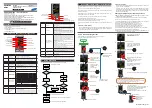
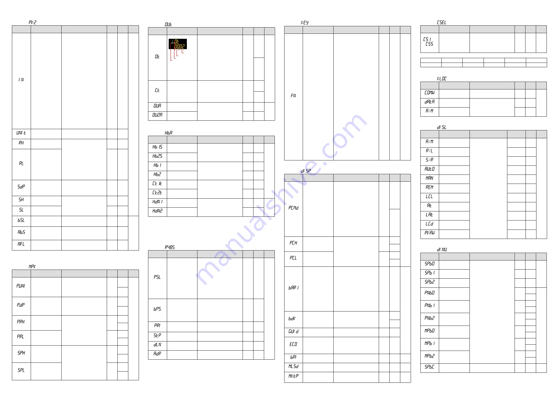
(OT)
Output type selection
Output type
00
Lit when the loop-2
parameter is displayed.
Symbol
The LP2 lamp is lit when
the loop-2 output type
selection parameter is
displayed.
00: OFF
01: OUT terminals (voltage pulse)
02: OUT terminals (current)
03: OUT terminals (relay)
06: OUT2 terminals (relay)
07: OUT2 terminals (voltage pulse)
08: OUT2 terminals (current)
Loop-1:
00.02
Loop-2:
00.08
(LP1)
EASY
(LP2)
(CT)
Control output cycle time
The LP2 lamp is lit when
the loop-2 control output
cycle time parameter is
displayed.
0.5 to 1000.0 s
30.0 s
(LP1)
(LP2)
(OU.A)
OUT current output
range
4-20: 4 to 20 mA
0-20: 0 to 20 mA
20-4: 20 to 4 mA
20-0: 20 to 0 mA
4-20
STD
(OU2.A)
OUT2 current output
range
4-20
■
Heater Break Alarm Setting Parameter
Menu symbol:
(HBA)
Parameter
symbol
Name of Parameter
Setting Range
Initial
value
User
setting
Display
level
(HB1.S)
Heater break alarm-1
function selection
0: Heater current measurement
1: Loop-1 side heater break alarm
2: Loop-2 side heater break alarm
1
EASY
(HB2.S)
Heater break alarm-2
function selection
1
(HB1)
Heater break alarm-1
current setpoint
OFF, 0.1 to 300.0 Arms
OFF
(HB2)
Heater break alarm-2
current setpoint
OFF
(CT1.T)
CT1
coil winding number ratio
1 to 3300
800
(CT2.T)
CT2
coil winding number ratio
800
(HDN1)
Heater break alarm-1
On-delay timer
0.00 to 99.59 (m.s)
0.00
STD
(HDN2)
Heater break alarm-2
On-delay timer
0.00
In cases where the current transformers manufactured by U.R.D. Co., Ltd are used, set
the following value for the coil winding number ratio.
CTL-6-S-H: 800
CTL-12L-30: 3000
■
RS-485 Communication Setting Parameter (E1-terminal Area)
Menu symbol:
(R485)
Parameter
symbol
Name of Parameter
Setting Range
Initial
value
User
setting
Display
level
(PSL)
Protocol selection
PCL: PC link communication
PCLSM: PC link communication (with
checksum)
LADR: Ladder communication
CO-M: Coordinated master station
CO-S: Coordinated slave station
MBASC: Modbus (ASCII)
MBRTU: Modbus (RTU)
CO-S1: Coordinated slave station
(Loop-1 mode)
CO-S2: Coordinated slave station
(Loop-2 mode)
P-P: Peer-to-peer communication
MBRTU
EASY
(BPS)
Baud rate
600: 600 bps
1200: 1200 bps
2400: 2400 bps
4800: 4800 bps
9600: 9600 bps
19200: 19.2k bps
38400: 38.4k bps
19200
(PRI)
Parity
NONE: None
EVEN: Even
ODD: Odd
EVEN
(STP)
Stop bit
1: 1 bit, 2: 2 bits
1
(DLN)
Data length
7: 7 bits, 8: 8 bits
8
(ADR)
Address
1 to 99
1
■ Key Action Setting Parameter
Menu symbol:
(KEY)
Parameter
symbol
Name of Parameter
Setting Range
Initial
value
User
setting
Display
level
(Fn)
User function key-n
action setting
OFF: Disable
A/M: AUTO/MAN switch
R/L1: REM/LCL switch
R/L2: Loop-2 REM/LCL switch
S/R: STOP/RUN switch
AUTO: Switch to AUTO
MAN: Switch to MAN
REM1: Switch to REM
LCL1: Switch to LCL
REM2: Switch to Loop-2 REM
LCL2: Switch to Loop-2 LCL
STOP: Switch to STOP
RUN: Switch to RUN
AT: Auto-tuning
LTUP: LCD brightness UP
LTDN: LCD brightness DOWN
BRI: Adjust LCD brightness
LCD: LCD backlight ON/OFF switch
LAT: Latch release
PID: PID tuning switch
A/M2: Loop-2 AUTO/MAN switch
S/R2: Loop-2 STOP/RUN switch
AUT2: Switch to Loop-2 AUTO
MAN2: Switch to Loop-2 MAN
STP2: Switch to Loop-2 STOP
RUN2: Switch to Loop-2 RUN
AT2: Loop-2 Auto-tuning
PID2: Loop-2 PID tuning switch
A/MS: Displaying loop AUTO/MAN switch
R/LS: Displaying loop REM/LCL switch
S/RS: Displaying loop STOP/RUN switch
AUTS: Switch to AUTO displaying loop
MANS: Switch to MAN displaying loop
REMS: Switch to REM displaying loop
LCLS: Switch to LCL displaying loop
STPS: Switch to STOP displaying loop
RUNS: Switch to RUN displaying loop
ATS: Displaying loop auto-tuning
PIDS: PID tuning switch displaying loop
P.RUN: Start of program operation
P.STP: Stop of program operation
PIDS
EASY
■ Display Function Setting Parameter
Menu symbol:
(DISP)
Parameter
symbol
Name of Parameter
Setting Range
Initial
value
User
setting
Display
level
(PCMD)
Active color PV display
switch
0: Fixed in white
1: Fixed in red
2: Link to alarm 1 (Alarm OFF: white,
Alarm ON: red)
3: Link to alarm 1 (Alarm OFF: red,
Alarm ON: white)
4: Link to alarm 1 or 2 (Alarm OFF:
white, Alarm ON: red)
5: Link to alarm 1 or 2 (Alarm OFF:
red, Alarm ON: white)
6: PV limit (Within range: white, Out
of range: red)
7: PV limit (Within range: red, Out of
range: white)
8: SP deviation (Within deviation:
white, Out of deviation: red)
9: SP deviation (Within deviation: red,
Out of deviation: white)
10: Link to DI (ON: red, OFF: white)
0
(LP1)
EASY
(LP2)
(PCH)
PV color change high
limit
Set a display value when in PV limit
or SP deviation.
-19999 to 30000 (Set a value within
the input range.)
Decimal point position depends on
the input type.
0
(LP1)
(LP2)
(PCL)
PV color change low limit
0
(LP1)
(LP2)
(BAR1)
Bar-graph display regis-
tration
0: Disable
1: Loop-1 OUT, 3: Loop-1 PV
4: Loop-1 SP, 5: Loop-1 deviation
6: Loop-2 OUT, 8: Loop-2 PV
9: Loop-2 SP, 10: Loop-2 deviation
18: PV terminals analog input
19: PV2 terminals analog input
22: Display loop OUT
24: Display loop PV
25: Display loop SP
26: Display loop Deviation
27: Loop-1 TSP, 28: Loop-1 TSP deviation
29: Loop-2 TSP, 30: Loop-2 TSP deviation
31: Display loop TSP
32: Display loop TSP deviation
5
STD
(BDV)
Bar-graph deviation
display band
0.0 to 100.0% of PV input range span
(EUS)
1.0 %
of PV
input
range
span
(LP1)
(LP2)
(GUID)
Guide display ON/OFF
OFF: Nondisplay, ON: Display
ON
(ECO)
Economy mode
OFF: Disable
1: Economy mode ON (All indications
except PV display OFF)
2: Economy mode ON (All indications OFF)
3: Brightness 10 % (whole indication)
OFF
(BRI)
Brightness
(Dark) 1 to 5 (Bright)
3
EASY
(MLSD)
Least significant digital
mask of PV display
OFF: With least significant digit
ON: Without least significant digit
OFF
STD
(MKTP)
Method for least signifi-
cant digital mask of PV
display
0: Rounding, 1: Rounding-off
0
STD
■ SELECT Display Setting Parameter
Menu symbol:
(CSEL)
Parameter
symbol
Name of Parameter
Setting Range
Initial
value
User
setting
Display
level
to
(CS1 to CS5)
SELECT Display-1 to -5
registration
Register the operation parameter (except
the Operation Mode) that is frequently mod-
ified to display it in the Operation Display.
OFF, 2301 to 5000, 6701 to 6710
For the setting range, see User's Manual
(IM 05P08D31-01EN).
OFF
Table
below
STD
Use the following table to record SELECT Display setting value.
Parameter
n=1
n=2
n=3
n=4
n=5
CSn
■ Key Lock Setting Parameter
Menu symbol:
(KLOC)
Parameter
symbol
Name of Parameter
Setting Range
Initial
value
User
setting
Display
level
(COM.W)
Communication write
enable/disable
OFF: Enable, ON: Disable
OFF
STD
(DATA)
Front panel parameter
data (▼,▲) key lock
OFF: Unlock, ON: Lock
OFF
(A/M)
Front panel A/M key lock
OFF
■ DI Function Registration Parameter
Menu symbol:
(DI.SL)
Parameter
symbol
Name of Parameter
Setting Range
Initial value
User
setting
Display
level
(A/M)
AUTO/MAN switch
Set an I relay number of
contact input.
Set “OFF” to disable the
function.
Standard terminals
DI1: 5025, DI2: 5026, DI3:
5027
Loop-1:5025
Loop-2:5027
STD
(R/L)
REMOTE/LOCAL switch
OFF
(S/R)
STOP/RUN switch
5026
(AUTO)
Switch to AUTO
OFF
(MAN)
Switch to MAN
OFF
(REM)
Switch to REMOTE
OFF
(LCL)
Switch to LOCAL
OFF
(AT)
Auto-tuning START/STOP
switch
OFF
(LAT)
Latch release
OFF
(LCD)
LCD backlight ON/OFF
switch
OFF
(PVRW)
PV red/white switch
OFF
■ DI Function Numbering Parameter
Menu symbol:
(DI.NU)
Parameter
symbol
Name of Parameter
Setting Range
Initial
value
User
setting
Display
level
(SP.B0)
Bit-0 of SP number
Set an I relay number of contact input.
Set “OFF” to disable the function.
Standard terminals
DI1: 5025, DI2: 5026, DI3: 5027
OFF
EASY
(SP.B1)
Bit-1 of SP number
OFF
(SP.B2)
Bit-2 of SP number
OFF
(PN.B0)
Bit-0 of PID number
OFF
(LP1)
STD
(LP2)
(PN.B1)
Bit-1 of PID number
OFF
(LP1)
(LP2)
(PN.B2)
Bit-2 of PID number
OFF
(LP1)
(LP2)
(MP.B0)
Bit-0 of manual preset
output number
OFF
(LP1)
(LP2)
(MP.B1)
Bit-1 of manual preset
output number
OFF
(LP1)
(LP2)
(MP.B2)
Bit-2 of manual preset
output number
OFF
(LP1)
(LP2)
(SP.BC)
Bit changing method of SP
number
0: Status switch 1
1: Status switch 2
0
STD


