
IM 05P08D31-11EN page 12/12
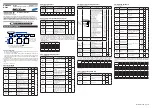
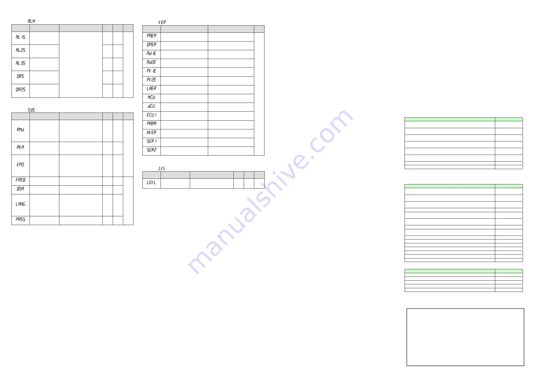
■ AL1-AL3 Function Registration Parameter
Menu symbol:
(ALM)
Parameter
symbol
Name of Parameter
Setting Range
Initial
value
User
setting
Display
level
(AL1.S)
AL1 function selection
Set an I relay number. For the items
other than below, see User's Manual
(IM 05P08D31-01EN).
Ex.) Set the number 4353 for AL1.S
to use the alarm 1.
Set “OFF” to disable the function.
No function: OFF
Loop-1 alarm 1: 4353
Loop-1 alarm 2: 4354
Loop-1 alarm 3: 4355
Loop-1 alarm 4: 4357
Loop-2 alarm 1: 4353
Loop-2 alarm 2: 4354
Loop-2 alarm 3: 4355
Loop-2 alarm 4: 4357
AUTO (OFF) / MAN (ON) status: 4193
REM (ON) / LCL (OFF) status: 4194
STOP (ON) / RUN (OFF) status: 4195
FAIL (Normally ON) output: 4256
4353
STD
(AL2.S)
AL2 function selection
4354
(AL3.S)
AL3 function selection
4355
(OR.S)
OUT relay function
selection
OFF
(OR2.S)
OUT2 relay function
selection
OFF
■ System Setting Parameter
Menu symbol:
(SYS)
Parameter
symbol
Name of Parameter
Setting Range
Initial
value
User
setting
Display
level
(R.MD)
Restart mode
Set how the controller should recover
from a power failure of 5 seconds or
more.
CONT: Continue action set before
power failure.
MAN: Start from MAN.
AUTO: Start from AUTO.
CONT
STD
(R.TM)
Restart timer
Set time between power on and the
instant where controller starts compu
-
tation.
0 to 10 s
0
(EPO)
Input error preset output
Set preset output value when the
input burnout or ADC error occurs.
Manual output is prioritized when the
input burnout occurs in MAN.
0: Preset output
1: 0% output
2: 100% output
0
(FREQ)
Power frequency
AUTO, 60: 60 Hz, 50: 50 Hz
AUTO
EASY
(QSM)
Quick setting mode
OFF: Disable
ON: Enable
ON
(LANG)
Guide display language
ENG: English
FRA: French
GER: German
SPA: Spanish
Depe-
nds
on the
model
and
suffix
codes
(PASS)
Password setting
0 (No password) to 65535
0
■ Error and Version Confirmation Parameter (for display only)
Menu symbol:
(VER)
Parameter
symbol
Name of Parameter
Status record
Display
level
(PA.ER)
Parameter error status
EASY
(OP.ER)
Option error status
(AD1.E)
A/D converter error status 1
(AD2.E)
A/D converter error status 2
(PV1.E)
PV input error status
(PV2.E)
PV2 input error status
(LA.ER)
Ladder error status
(MCU)
MCU version
(DCU)
DCU version
(ECU1)
ECU-1 version (E1-terminal area)
(PARA)
Parameter version
(H.VER)
Product version
(
SER1
)
Serial number 1
(SER2)
Serial number 2
■ Parameter Display Level Parameter
Menu symbol:
(LVL)
Parameter
symbol
Name of Parameter
Setting Range
Initial
value
User
setting
Display
level
(LEVL)
Parameter display level
EASY: Easy setting mode
STD: Standard setting mode
PRO: Professional setting mode
STD
EASY
* For Professional setting mode, see User’s Manual (IM 05P08D31-01EN).
Trademarks
● Our product names or brand names mentioned in this manual are
the trademarks or registered trademarks of Yokogawa Electric Corporation.
● Adobe, Acrobat, and Postscript are either registered trademarks or trademarks
of Adobe Systems Incorporated.
● Ethernet is a registered trademark of XEROX Corporation in the United States.
● Modbus is a registered trademark of Schneider Electric.
● PROFIBUS-DP is a registered trademark of PROFIBUS User Organization.
● DeviceNet is a registered trademark of Open DeviceNet Vendor Association.
● CC-Link is a registered trademark of CC-Link Partner Association.
● We do not use the TM or ® mark to indicate these trademarks or
registered trademarks in this manual.
● All other product names mentioned in this manual are trademarks
or registered trademarks of their respective companies.
• Authorised Representative in the EEA
Yokogawa Europe BV. (Address: Euroweg 2 , 3825 HD Amersfoort, The
Netherlands) is the Authorised Representative of Yokogawa Electric Corporation
for this Product in the EEA.
• Printed Manuals
Model
Description
UT35A, UT32A Digital Indicating Controller (Panel Mounting Type) Operation Guide
«
Standard Code Model
»
IM 05P01D31-11EN
UT35A, UT32A Digital Indicating Controller (Panel Mounting Type) Operation Guide
«
Detailed Code Model
»
IM 05P01D31-15EN
UT35A/MDL, UT32A/MDL Digital Indicating Controller (DIN Rail Mounting Type)
Operation Guide
«
Standard Code Model
»
IM 05P01D81-11EN
UT32A-D Digital Indicating Controller (Dual-loop, Panel Mounting Type)
Operation Guide
«
Standard Code Model
»
IM 05P08D31-11EN
UT32A-D/MDL Digital Indicating Controller (Dual-loop, DIN Rail Mounting Type)
Operation Guide
«
Standard Code Model
»
IM 05P08D81-11EN
UT35A/RSP, UT32A/RSP Digital Indicating Controller (Non-isolated Remote
Input, Panel Mounting Type) Operation Guide
«
Standard Code Model
»
IM 05P01D31-81EN
UT32A Digital Indicating Controller Operation Guide
«
Entry Model
»
IM 05P01F31-11EN
Precautions on the Use of the UTAdvanced Series
IM 05P01A01-11EN
• Electronic Manuals
You can download the latest manuals from the following website:
URL: http://www.yokogawa.com/ns/ut/im/
Model
Description
UT35A, UT32A Digital Indicating Controller (Panel Mounting Type) Operation Guide
«
Standard Code Model
»
IM 05P01D31-11EN
UT35A, UT32A Digital Indicating Controller (Panel Mounting Type) Operation Guide
«
Detailed Code Model
»
IM 05P01D31-15EN
UT35A/MDL, UT32A/MDL Digital Indicating Controller (DIN Rail Mounting Type)
Operation Guide
«
Standard Code Model
»
IM 05P01D81-11EN
UT35A/UT32A Digital Indicating Controller User’s Manual
IM 05P01D31-01EN
UT32A-D Digital Indicating Controller (Dual-loop, Panel Mounting Type)
Operation Guide
«
Standard Code Model
»
IM 05P08D31-11EN
UT32A-D/MDL Digital Indicating Controller (Dual-loop, DIN Rail Mounting Type)
Operation Guide
«
Standard Code Model
»
IM 05P08D81-11EN
UT32A-D, UT32A-D/MDL Digital Indicating Controller User’s Manual
IM 05P08D31-01EN
UT35A/RSP, UT32A/RSP Digital Indicating Controller (Non-isolated Remote
Input, Panel Mounting Type) Operation Guide
«
Standard Code Model
»
IM 05P01D31-81EN
UT32A Digital Indicating Controller Operation Guide
«
Entry Model
»
IM 05P01F31-11EN
UT32A Digital Indicating Controller User’s Manual
«
Entry Model
»
IM 05P01F31-01EN
UTAdvanced Series Communication Interface (RS-485, Ethernet) User’s Manual IM 05P07A01-01EN
UTAdvanced Series Communication Interface (Open Network) User’s Manual
IM 05P07A01-02EN
LL50A Parameter Setting Software Installation Manual
IM 05P05A01-01EN
LL50A Parameter Setting Software User’s Manual
IM 05P05A01-02EN
Precautions on the Use of the UTAdvanced Series
IM 05P01A01-11EN
• General Specification
Model
Description
UT35A, UT32A Digital Indicating Controller (Panel Mounting Type)
GS 05P01D31-01EN
UT35A/MDL, UT32A/MDL Digital Indicating Controller (DIN Rail Mounting Type) GS 05P01D81-01EN
UT32A-D Digital Indicating Controller (Dual-loop, Panel Mounting Type)
GS 05P08D31-01EN
UT32A-D/MDL Digital Indicating Controller (Dual-loop, DIN Rail Mounting Type) GS 05P08D81-01EN
LL50A Parameter Setting Software
GS 05P05A01-01EN
*
The last two characters of the manual number and general specification number indicate the
language in which the manual is written.


