

IM 05P08D31-11EN page 2/12
4. Hardware Specifications
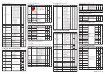
WARNING
This instrument is for Measurement Category No.1.
Do not use it for measurements in locations falling under Measure-
ment Categories No.2, No.3, and No.4.
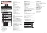
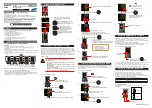
Internal Wiring
Outlet
Entrance IV
Cable
III
T
O( I )
II
Category
IEC/EN/CSA
/
UL
61010-1
EN 61010-2-030
Remarks
No.1
Measurement
Category I
O (Other)
For measurements performed on circuits not direct
-
ly connected to MAINS.
No.2
Measurement
Category II
Measurement
Category II
For measurements performed on circuits directly
connected to the low-voltage installation.
No.3
Measurement
Category III
Measurement
Category III
For measurements performed in the building instal-
lation.
No.4
Measurement
Category IV
Measurement
Category IV
For measurements performed at the source of the
low-voltage installation.
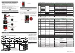
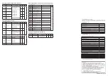
■
Input Specifications
●Universal Input (Equipped as standard)
• Number of inputs: 1
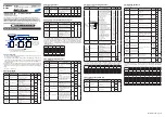
• Input type, instrument range, and measurement accuracy: See the table below,
Input Type
Instrument Range
Accuracy
ºC
ºF
Thermo-
couple
K
-270.0 to 1370.0ºC -450.0 to 2500.0ºF ±0.1% of instrument range ±1 digit for
0°C or more
±0.2% of instrument range ±1 digit for
less than 0°C
±2% of instrument range ±1 digit for
less than -200.0°C of thermocouple K
±1% of instrument range ±1 digit for
less than -200.0°C of thermocouple T
-270.0 to 1000.0ºC -450.0 to 2300.0ºF
-200.0 to 500.0ºC -200.0 to 1000.0ºF
J
-200.0 to 1200.0ºC -300.0 to 2300.0ºF
T
-270.0 to 400.0ºC
-450.0 to 750.0ºF
0.0 to 400.0ºC
-200.0 to 750.0ºF
B
0.0 to 1800.0ºC
32 to 3300ºF
±0.15% of instrument range ±1 digit
for 400°C or more
±5% of instrument range ±1 digit for
less than 400°C
S
0.0 to 1700.0ºC
32 to 3100ºF
±0.15% of instrument range ±1 digit
R
0.0 to 1700.0ºC
32 to 3100ºF
N
-200.0 to 1300.0ºC -300.0 to 2400.0ºF
±0.1% of instrument range ±1 digit
±0.25% of instrument range ±1 digit
for less than 0°C
E
-270.0 to 1000.0ºC -450.0 to 1800.0ºF ±0.1% of instrument range ±1 digit for
0°C or more
±0.2% of instrument range ±1 digit for
less than 0°C
±1.5% of instrument range ±1 digit for
less than -200.0°C of thermocouple E.
L
-200.0 to 900.0ºC
-300.0 to 1600.0ºF
U
-200.0 to 400.0ºC
-300.0 to 750.0ºF
0.0 to 400.0ºC
-200.0 to 1000.0ºF
W
0.0 to 2300.0ºC
32 to 4200ºF
±0.2% of instrument range ±1 digit
(Note 2)
Platinel 2
0.0 to 1390.0ºC
32.0 to 2500.0ºF ±0.1% of instrument range ±1 digit
PR20-40
0.0 to 1900.0ºC
32 to 3400ºF
±0.5% of instrument range ±1 digit for
800°C or more
Accuracy is not guaranteed for less
than 800°C.
W97Re3-
W75Re25
0.0 to 2000.0ºC
32 to 3600ºF
±0.2% of instrument range ±1 digit
RTD
JPt100
-200.0 to 500.0ºC
-300.0 to 1000.0ºF ±0.1% of instrument range ±1 digit
(Note 1)
-150.00 to 150.00ºC -200.0 to 300.0ºF ±0.1% of instrument range ±1 digit
Pt100
-200.0 to 850.0ºC
-300.0 to 1560.0ºF ±0.1% of instrument range ±1 digit
(Note 1)
-200.0 to 500.0ºC
-300.0 to 1000.0ºF
-150.00 to 150.00ºC -200.0 to 300.0ºF ±0.1% of instrument range ±1 digit
Standard signal
0.400 to 2.000 V
±0.1% of instrument range ±1 digit
1.000 to 5.000 V
4.00 to 20.00 mA
DC voltage/current
0.000 to 2.000 V
0.00 to 10.00 V
0.00 to 20.00 mA
-10.00 to 20.00 mV
0.0 to 100.0 mV
The accuracy is that in the standard operating conditions: 23±2°C, 55±10%RH, and power
frequency at 50/60 Hz.
Note
1: ±0.3°C ±1 digit in the range between 0 and 100°C, ±0.5°C ±1 digit in the range
between -100 and 200°C.
Note 2: W: W-5% Re/W-26% Re(Hoskins Mfg.Co.). ASTM E988
• Input sampling (control) period: 200 ms
• Burnout detection:
Functions at TC, RTD, and standard signal.
Upscale, downscale, and off can be specified.
For standard signal, burnout is determined to have occurred if it is 0.1 V or 0.4
mA or less.
• Input bias current: 0.05 µA (for TC or RTD)
• Measured current (RTD): About 0.16 mA
• Input resistance:
TC or mV input: 1 MΩ or more
V input: About 1 MΩ
mA input: About 250 Ω
• Allowable signal source resistance:
TC or mV input: 250 Ω or less
Effects of signal source resistance: 0.1 µV/Ω or less
DC voltage input: 2 kΩ or less
Effects of signal source resistance: About 0.01%/100 Ω
• Allowable wiring resistance:
RTD input: Max. 150 Ω/wire (The conductor resistance between the three wires
shall be equal.)
Wiring resistance effect: ±0.1ºC/10 Ω
• Allowable input voltage/current:
TC, mV, mA and RTD input: ±10 V DC
V input: ±20 V DC
mA input: ±40 mA
• Noise rejection ratio:
Normal mode: 40 dB or more (at 50/60 Hz)
Common mode: 120 dB or more (at 50/60 Hz)
For 100-240 V AC, the power frequency can be set manually. Automatic
detection is also available.
For 24 V AC/DC, the power frequency can be set manually.
• Reference junction compensation error:
±1.0ºC (15 to 35ºC), ±1.5ºC (-10 to 15ºC and 35 to 50ºC)
• Applicable standards: JIS/IEC/DIN (ITS-90) for TC and RTD
■
Contact Input Specifications
• Number of inputs: See the table of Model and Suffix Codes.
• Input type: No-voltage contact input or transistor contact input
• Input contact rating: 12 V DC, 10 mA or more
Use a contact with a minimum on-current of 1 mA or less.
• ON/OFF detection:
No-voltage contact input:
Contact resistance of 1 kΩ or less is determined as “ON” and contact
resistance of 50 kΩ or more as “OFF.”
Transistor contact input:
Input voltage of 2 V or less is determined as “ON” and leakage current must
not exceed 100 µA when “OFF.”
• Minimum status detection hold time: Control 50 ms
• Use: SP switch, operation mode switch, and event input
■
Analog Output Specifications (OUT, OUT2)
• Number of outputs:
Control output: 2
• Output type: Current output or voltage pulse output
• Current output: 4 to 20 mA DC or 0 to 20 mA DC/load resistance of 600 Ω or less
• Current output accuracy: ±0.1% of span (±5% of span for 1 mA or less)
The accuracy is that in the standard operating conditions: 23±2°C, 55±10%RH,
and power frequency at 50/60 Hz.
• Voltage pulse output:
Use: Time proportional output
On-voltage: 12 V or more/load resistance of 600 Ω or more
Off-voltage: 0.1 V DC or less
Time resolution: 10 ms or 0.1% of output, whichever is larger
■
Relay Contact Output Specifications (OUT, OUT2)
• Contact type and number of outputs:1a; 2 points (common is independent)
• Contact rating: 240 V AC, 3A or 30 V DC, 3A (resistance load)
• Use: Time proportional output, ON/OFF output
• Time resolution of control output: 10 ms or 0.1% of output, whichever is larger
Note: The control output should always be used with a load of 10 mA or more.
■
Alarm Relay Contact Output Specifications (ALM)
• Contact type and number of outputs: 3 points (common is independent)
• Contact rating: 240 V AC, 1A or 30 V DC, 1 A (resistance load)
• Use: Alarm output, FAIL output, etc.
Note: The alarm output should always be used with a load of 1 mA or more.
■
Heater Break Alarm Specifications (for /HA option)
• Number of inputs: 2
• Number of outputs: 2 (transistor contact output)
• Use: Measures the heater current using an external current transformer (CT) and
generates a heater break alarm when the measured value is less than the break
detection value.
• Current transformer input resistance: About 9.4 Ω
•
Current transformer input range: 0.0 to 0.1 Arms (0.12 Arms or more cannot be applied.)
• Heater current setting range: OFF, 0.1 to 300.0 Arms
Heater current measured value display range: 0.0 to 360.0 Arms
Note: The CT ratio can be set. CT ratio setting range: 1 to 3300
• Recommended CT: CT from U.R.D., Ltd.
CTL-6-S-H: CT ratio 800, measurable current range: 0.1 to 80.0 Arms
CTL-12L-30: CT ratio 3000, measurable current range: 0.1 to 180.0 Arms
• Heater current measurement period: 200 ms
• Heater current measurement accuracy: ±5% of current transformer input range
span ± 1digit (CT error is not included.)
•
Heater current detection resolution: Within 1/250 of current transformer input range span
• Break detection On-time: Min. 0.2 second (for time proportional output)
■ Safety and EMC Standards
• Safety:
Compliant with IEC/EN 61010-1 (CE), IEC/EN 61010-2-201 (CE), IEC/EN 61010-
2-030 (CE), approved by CAN/CSA C22.2 No. 61010-1 (CSA), approved by UL
61010-1.
Installation category: II
Pollution degree: 2
Measurement category: I (CAT I) (UL, CSA)
O (Other) (CE)
Rated measurement input voltage: Max. 10 V DC
Rated transient overvoltage: 1500 V (*)
* This is a reference safety standard value for measurement category I of CSA/UL 61010-
1, and for measurement category O of IEC/EN 61010-2-030. This value is not necessarily a
guarantee of instrument performance.
• EMC standards:
Compliant with CE marking
EN 61326-1 Class A, Table 2 (For use in industrial locations),
EN 61326-2-3
* The instrument continues to operate at a measurement accuracy of within ±20% of the
range during testing.
EN 55011 Class A, Group 1
EN 61000-3-2 Class A
EN 61000-3-3
EMC Regulatory Arrangement in Australia and New Zealand (for all model includ-
ing LL50A)
EN 55011 Class A, Group 1
• KC marking:
Electromagnetic wave interference prevention standard, electromagnetic wave
protection standard compliance
■ Construction, Installation, and Wiring
• Dust-proof and drip-proof: IP66 (for front panel) (Not available for side-by-side
close mounting.)
• Material: Polycarbonate (Flame retardancy: UL94V-0)
• Case color: White (Light gray) or Black (Light charcoal gray)
• Weight: 0.5 kg or less
• External dimensions (mm): 48 (W) × 96 (H) × 65 (depth from the panel face)
(Depth except the projection on the rear panel)
• Installation: Direct panel mounting; mounting bracket, one each for upper and
lower mounting
• Panel cutout dimensions (mm): 45
+0.6/0
(W) × 92
+0.8/0
(H)
•
Mounting attitude: Up to 30 degrees above the horizontal. No downward titling allowed.
• Wiring: M3 screw terminal with square washer (for signal wiring and power wiring)
■ Power Supply Specifications and Isolation
• Power supply:
Rated voltage: 100-240 V AC (+10%/-15%), 50/60 Hz
24 V AC/DC (+10%/-15%) (for /DC option)
• Power consumption: 15 VA (DC:7 VA, AC: 11 VA if /DC option is specified)
• Data backup: Nonvolatile memory
• Power holdup time: 20 ms (for 100 V AC drive)
• Withstanding voltage
Between primary terminals and secondary terminals: 2300 V AC for 1 minute (UL, CSA)
Between primary terminals and secondary terminals: 3000 V AC for 1 minute (CE)
Between primary terminals: 1500 V AC for 1 minute
Between secondary terminals: 500 V AC for 1 minute
(Primary terminals: Power* and relay output terminals; Secondary terminals:
Analog I/O signal terminals, contact input terminals, communication terminals
and functional grounding terminals.)
*: Power terminals for 24V AC/DC models are the secondary terminals.
• Insulation resistance: Between power supply terminals and a grounding terminal
20 MΩ or more at 500 V DC
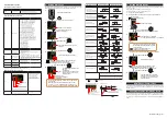
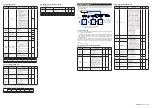
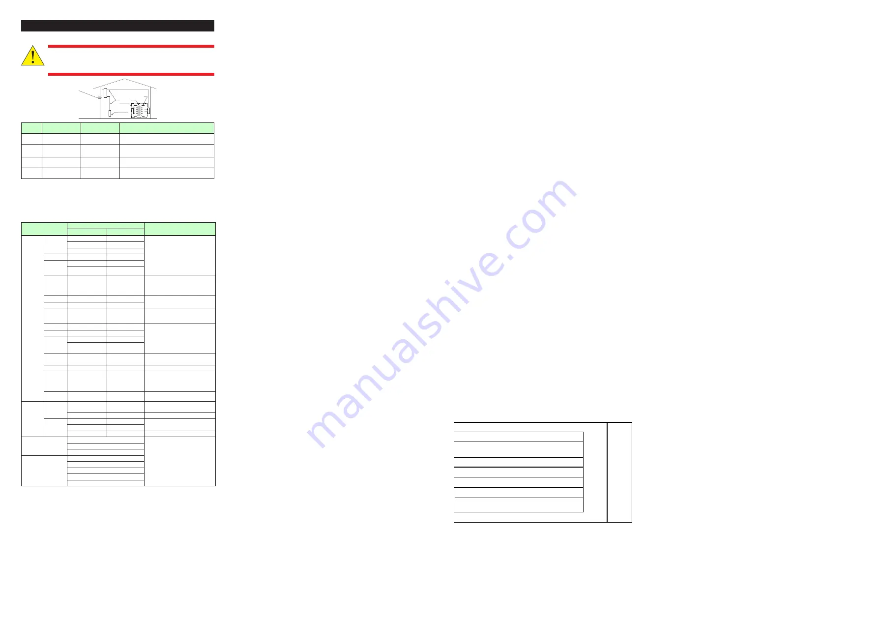
• Isolation specifications
The circuits divided by lines are insulated mutually.
Control (analog) output terminal (OUT, OUT2)
(not isolated between the analog output terminals)
PV1 (universal) input terminal
PV2 (universal) input terminal
Control relay (2 a-contact) output terminal (OUT, OUT2)
Alarm-1 relay (a-contact) output terminal
Alarm-2 relay (a-contact) output terminal
Alarm-3 relay (a-contact) output terminal
Internal
circuits
Power
supply
Contact input terminal (3 points)
RS485 communication terminal
Current transformer input terminal
■ Environmental Conditions
Normal Operating Conditions:
• Ambient temperature: -10 to 50°C (side-by-side mounting: -10 to 40 °C)
• Ambient humidity: 20 to 90% RH (no condensation allowed)
• Magnetic field: 400 A/m or less
• Continuous vibration at 5 to 9 Hz: Half amplitude of 1.5 mm or less, 1oct/min for 90
minutes each in the three axis directions
Continuous vibration at 9 to 150 Hz: 4.9 m/s
2
or less, 1oct/min for 90 minutes each
in the three axis directions
• Short-period vibration: 14.7 m/s
2
, 15 seconds or less
• Shock: 98 m/s
2
or less, 11 ms
• Altitude: 2000 m or less above sea level
• Warm-up time: 30 minutes or more after the power is turned on
• Startup time: Within 10 seconds
*: The LCD (a liquid crystal display) is used for a display portion of this product.
The LCD has a characteristic that the display action becomes late at the low
temperature. However, the control function is not affected.
Transportation and Storage Conditions:
• Temperature: -25 to 70ºC
• Temperature change rate: 20ºC/h or less
• Humidity: 5 to 95% RH (no condensation allowed)
Effects of Operating Conditions
• Effect of ambient temperature:
Voltage or TC input: ±1 µV/ºC or ±0.01% of F.S./ºC, whichever is larger
Current input: ±0.01% of F.S./ºC
RTD input: ±0.05ºC/ºC (ambient temperature) or less
Analog output: ±0.02% of F.S./ºC or less
• Effect of power supply voltage fluctuation
Analog input: ±0.05% of F.S. or less
Analog output: ±0.05% of F.S. or less
(Each within rated voltage range)


