
IM 05P08D31-11EN page 3/12
5. How to Connect Wires
WARNING
• Wiring work must be carried out by a person with basic electrical
knowledge and practical experience.
• Be sure to turn OFF the power supply to the controller before
wiring to avoid an electric shock. Use a tester or similar device to
ensure that no power is being supplied to a cable to be connected.
• For the wiring cable, the temperature rating is 75 °C or more.
• As a safety measure, always install a circuit breaker (an IEC
60947-compatible product, 5 A, 100 V or 220 V AC) in an easily
accessible location near the instrument. Moreover, provide
indication that the switch is a device for turning off the power to
the instrument.
• Install the power cable keeping a distance of more than 1 cm
from other signal wires.
• The power cable is required to meet the IEC standards concerned or
the requirements of the area in which the instrument is being installed.
• Wiring should be installed to conform to NEC (National Electrical
Code: ANSI/NFPA-70) or the wiring construction standards in
countries or regions where wiring will be installed.
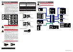
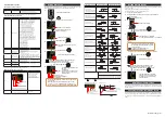
• Since the insulation provided to each relay output terminal is
Functional insulation, provide Reinforced insulation to the
external of the device as necessary. (Refer to the drawing below.)
This product
Functional
insulation
A safety
voltage circuit
A safety
voltage circuit
This product
Reinforced insulation
Reinforced insulation
Functional
insulation
A hazardous
voltage circuit
A hazardous
voltage circuit
A safety
voltage circuit
A safety
voltage circuit
This product
Reinforced insulation
Reinforced insulation
Functional
insulation
A hazardous
voltage circuit
A hazardous
voltage circuit
A hazardous
voltage circuit
A hazardous
voltage circuit
CAUTION
• When connecting two or more crimp-on terminal lugs to the
single terminal block, bend the crimp-on terminal lugs before
tightening the screw.
• Note that the wiring of two or more crimp-on terminal lugs to the
single high-voltage terminal of the power supply and relay, etc.
does not comply with the safety standard.
CAUTION
• Provide electricity from a single-phase power supply. If the
power is noisy, install an isolation transformer on the primary
side, and use a line filter on the secondary side. When measures
against noise are taken, do not install the primary and secondary
power cables close to each other.
• If there is a risk of external lightning surges, use a lightning
arrester etc.
• For TC input, use shielded compensating lead wires for wiring.
For RTD input, use shielded wires that have low conductor
resistance and cause no significant differences in resistance
between the three wires.
• Since the control output relay has a life span (resistance load of
100,000 times), use the auxiliary relay to perform ON/OFF control.
• The use of inductance (L) loads such as auxiliary relays, motors
and solenoid valves causes malfunction or relay failure; always
insert a CR filter for use with alternating current or a diode for
use with direct current, as a spark-removal surge suppression
circuit, into the line in parallel with the load.
• After completing the wiring, the terminal cover is recommended
to use for the instrument.
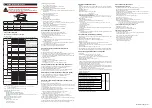
● Recommended Crimp-on Terminal Lugs
(A)
(F)
(ød
)
5.5 3.3
Recommended tightening torque: 0.6 N·m
Applicable wire size: Power supply wiring 1.25 mm
2
or more
Applicable terminal lug Applicable wire size mm
2
(AWG#)
(φ d)
(A)
(F)
M3
0.25 to 1.65 (22 to 16)
3.3
5.5
4.2
● Cable Specifications and Recommended Cables
Purpose
Name and Manufacturer
Power supply, relay contact outputs
600 V Grade heat-resistant PVC insulated wires, JIS C
3317(HIV), 0.9 to 2.0 mm
2
Thermocouple
Shielded compensating lead wires, JIS C 1610
For thermocouple input (PV input and remote input with direct
input), shielded compensating lead wire of cross-sectional area
less than or equal to 0.75 mm
2
is recommended. If the cross-
sectional area is wide, the reference junction compensation
error may be large.
RTD
Shielded wires (three/four conductors), UL2482 (Hitachi Cable)
Other signals (other than contact input/output)
Shielded wires
Other signals (contact input/output)
Unshielded wires
RS-485 communication
Shielded wires
Ethernet communication
100 BASE-TX (CAT-5)/10 BASE-T
PROFIBUS-DP communication
Dedicated cable for PROFIBUS-DP (Shielded two-wires)
DeviceNet communication
Dedicated cable for DeviceNet (Shielded five-wires)
CC-Link communication
Dedicated cable for CC-Link (Shielded three-wires)
PROFIBUS-DP/CC-Link Connector (wiring side) (Part number: A1987JT)
DeviceNet Connector (wiring side) (Part number: L4502BW)
Recommended tightening torque: 0.5 to 0.6 N·m
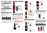
DC Relay Wiring
R
External DC power supply
Relay
UT32A-D
UT’s contact
Diode
(Mount it directly
to the relay coil
terminal (socket).)
Relay
(Use one with a relay coil rating
less than the UT’s contact rating.)
AC Relay Wiring
UT32A-D
R
UT’s contact
CR filter
(Mount it directly
to the relay coil
terminal (socket).)
External AC power supply
Relay
(Use one with a relay coil
rating less than the UT’s
contact rating.)
Transistor Output Wiring
power
+ –
UT
DO
Load
COM
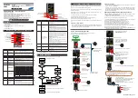
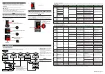
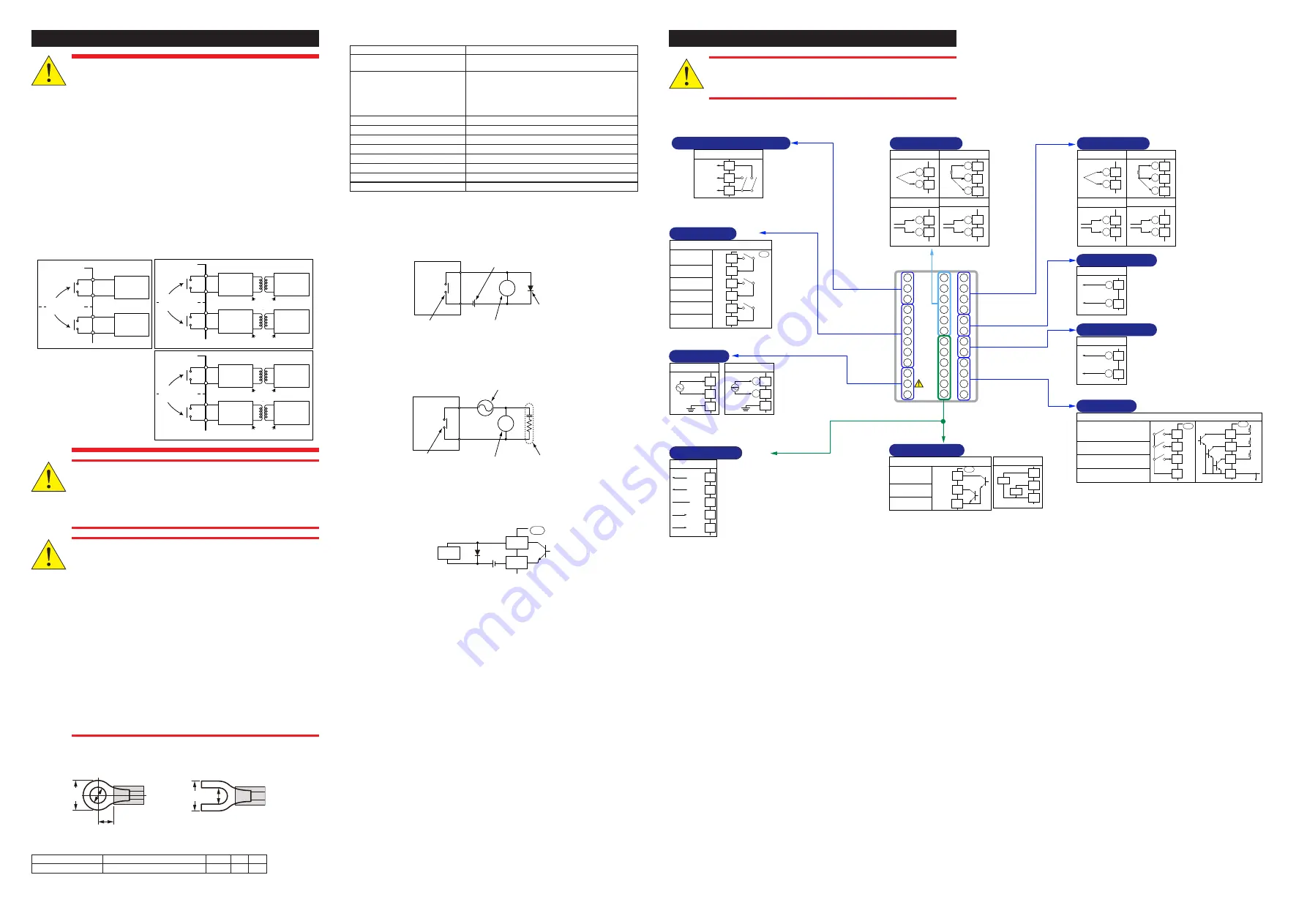
6. Terminal Wiring Diagrams
CAUTION
• Do not use an unassigned terminal as the relay terminal.
Do not use a 100-240 V AC power supply for the 24 V AC/DC
model; otherwise, the instrument will malfunction.
■ UT32A-D
TC input
RTD input
Voltage (mV, V) input
A
+
-
+
-
Current (mA) input
+
-
B
b
111
301
302
303
304
305
306
307
308
309
310
311
312
201
202
203
204
205
206
207
208
209
210
101
102
103
104
105
106
107
108
109
110
211
212
101
-112
301
-312
201
-212
302
303
301
302
303
302
303
303
304
PV2
Contact output
External contact output (relay)
AL3
AL2
AL1
Relay contact rating: 240 V AC, 1 A
30 V DC, 1 A (resistance load)
Alarm-3 output
(PV high limit)
Alarm-2 output
(PV low limit)
Alarm-1 output
(PV high limit)
Common
Common
Common
UT
104
105
106
107
108
109
ALM
Factory default:
PV input type is
0-10V DC.
Loop-1 PV input
Loop-2 PV input
TC input
RTD input
Voltage (mV, V) input
A
+
-
+
-
Current (mA) input
+
-
B
b
202
203
201
202
203
202
203
203
204
PV1
Factory default:
PV input type is
undefined.
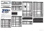
(Option code /HA)
Heater break alarm
Heater current detection input
CT1
CT2
COM
310
311
312
HBA
External contact output (transistor)
Transistor contact rating: 24 V DC, 50 mA
Heater break alarm-1
output
Heater break alarm-2
output
Common
HAL1
HAL2
COM
UT
307
308
309
Loop-1 and Loop-2 control output
Relay contact output
NO
NO
COM
Contact rating: 240 V AC, 3 A
30 V DC, 3 A (resistance load)
101
102
103
Factory default: Control output is relay.
OUT
OUT2
112
Power supply
24 V AC/DC power supply
-
+
100-240 V AC power supply
Allowable range:
100-240 V AC (+10%/-15%)
(free voltage)
50/60 Hz shared
N
L
(24 V AC/DC power supply:
Option code /DC)
110
111
110
111
112
112
N
L
Current/voltage pulse output
0-20 mA DC,
4-20 mA DC,
Voltage pulse (12 V)
-
Loop-2 control output
+
205
206
OUT2
Control output is relay at factory default.
Current output range can be changed.
Loop-1 control output
Current/voltage pulse output
0-20 mA DC,
4-20 mA DC,
Voltage pulse (12 V)
+
-
207
208
OUT
Control output is relay at factory default.
Current output range can be changed.
RS-485
SDB(+)
SDA(-)
RDB(+)
RDA(-)
SG
RS-485 communication
(Suffix code:
Type 2=1)
307
308
309
310
311
RS485
DI
Contact input
Contact rating: 12 V DC, 10 mA or more
External contact input
DI3
DI2
DI1
COM
Common
DI3
DI2
DI1
COM
+5V
+5V
+5V
No-voltage
contact
Transistor contact
UP
UP
209
210
211
212
209
210
211
212
Functions can be changed.
Loop-1 AUTO when DI1=ON
Loop-1 MAN when DI1=OFF
Loop-2 AUTO when DI3=ON
Loop-2 MAN when DI3=OFF
Loop-1 and Loop-2 STOP when DI2=ON
Loop-1 and Loop-2 RUN when DI2=OFF


