
IM 05P08D31-11EN page 5/12
Contents
1. Names and Functions of Display Parts
2. Setup Procedure
3. Quick Setting Function (Setting of Input and Output)
4. Setting Alarm Type
5. Setting Alarm Setpoint
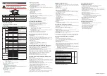
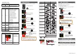
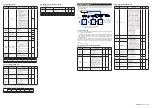
1. Names and Functions of Display Parts
(1) PV display
(2) Group display
(9) Status indicator
(10) Security indicator
(11) Ladder operation
indicator
(3) Symbol display
(5) Bar-graph display
(6) Event indicator
(7) Key navigation indicator
(8) Parameter display
level indicator
(4) Data display
(12) Loop-2 indicator
(2) + (3) + (4) : Setpoint display
No. in figure
Name
Description
(1)
PV display
(white or red)
Displays PV.
Displays an error code if an error occurs.
Displays the scrolling guide in the Menu Display and Parameter
Setting Display when the guide display ON/OFF is set to ON.
(2)
Group display (green)
Displays a group number (1 to 4 or R) and terminal area (E1).
1 to 4 represent SP numbers in the Operation Display.
R and E1 are displayed in the Parameter Setting Display.
(3)
Symbol display (orange) Displays a parameter symbol.
(4)
Data display (orange) Displays a parameter setpoint and menu symbol.
(5)
Bar-graph display
(orange)
Displays control output value (OUT) and measured input value (PV).
The data to be displayed can be set by the parameter.
Initial value: Deviation
(6)
Event indicator
(orange)
Lit when the alarms 1 to 4 occur.
Event displays other than alarms can be set by the parameter.
(7)
Key navigation indica-
tor (green)
Lit or blinks when the Up/Down or Left/Right arrow key operation
is possible.
(8)
Parameter display level
indicator (green)
Displays the setting conditions of the parameter display level func-
tion.
Parameter display level
EASY
PRO
Easy setting mode
Lit
Unlit
Standard setting mode
Unlit
Unlit
Professional setting mode
Unlit
Lit
(9)
Status indicator
(green and red)
Displays the operating conditions and control status.
Indicator
Description
REM
Lit when in remote mode (REM).
STOP
Lit when in stop mode (STOP).
MAN
Lit when in manual mode (MAN).
Blinks during auto-tuning.
(10)
Security indicator (red) Lit if a password is set. The setup parameter settings are locked.
(11)
Ladder operation
indicator (green)
Lit while the ladder operation is executed.
(12)
Loop 2 indicator
(LP2 lamp)
(green)
In the Operation Display, the LP2 lamp is lit while the Loop-2 PV is
displayed on PV display.
In the Parameter Setting Display, the LP2 lamp indicates the
loop of displayed menu symbol or parameter symbol. The LP2
lamp is lit while the Loop-2 menu symbol or parameter symbol is
displayed.
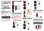
(4) Light-loader interface
(5) A/M key
(6) User function keys
(1) DISP key
(2) PARA key
(3) SET/ENTER key
Up/Down/Left/Right arrow keys
No. in figure
Name
Description
(1)
DISP key
Used to switch the Operation Displays.
Press the key in the Operation Display to switch the provided
Operation Displays.
Press the key in the Menu Display or Parameter Setting Display
to return to the Operation Display.
(2)
PARA key
Hold down the key for 3 seconds to move to the Operation
Parameter Setting Display.
Hold down the key and the Left arrow key simultaneously for 3
seconds to move to the Setup Parameter Setting Display.
Press the key in the Parameter Setting Display to return to the
Menu Display. Press the key once to cancel the parameter set-
ting (setpoint is blinking).
(3)
SET/ENTER key
Up/Down/Left/Right
arrow keys
SET/ENTER key
Press the key in the Menu Display to move to the Parameter
Setting Display of the Menu. Press the key in the Parameter
Setting Display to transfer to the parameter setting mode (set-
point is blinking), and the parameter can be changed.
Press the key during parameter setting mode to register the
setpoint.
Up/Down/Left/Right arrow keys
Press the Left/Right arrow keys in the Menu Display to switch
the Displays.
Press the Up/Down/Left/Right arrow keys in the Parameter
Setting Display to switch the Displays.
Press the Up/Down arrow keys during parameter setting mode
(setpoint is blinking) to change a setpoint.
Press the Left/Right arrow keys during parameter setting mode
(setpoint is blinking) to move between digits according to the parameter.
(4)
Light-loader interface
It is the communication interface for the adapter cable used when
setting and storing parameters from a PC. The LL50A Parameter
Setting Software (sold separately) is required.
(5)
A/M key
Used to switch between AUTO and MAN modes.
The setting is switched between AUTO and MAN each time the
key is pressed.
(6)
User function keys
Fn key. The user can assign a function to the key. The function is
set by the parameter.
Note: The communication connector (maintenance port) for LL50A Parameter Setting Software is
on the top of the unit.
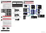
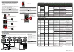
2. Setup Procedure
The following flowchart shows the setup procedure for UT32A-D.
Install and wire a controller.
Monitoring and control of regular operations
Adjust PID using auto-tuning or manually for PID control.
Other setup
Operation
NO
NO
NO
YES
YES
YES
Set the other parameters as needed.
PID tuning
Input setup
Output setup
Installation
and wiring
Power ON
Control type setup
Control type setup
Input/output setup
Valve position
adjustment
Use
Quick setting
function?
Position
proportional
type?
Position
proportional
type?
For Position proportional type
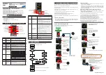
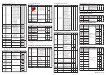
3. Quick Setting Function (Setting of Input and Output)
The Quick setting function is a function to easily set the basic function of the control-
ler.
Turn on the controller to start the Quick setting function.
This function allows you to easily set the control type, input, and output, and quickly
start the control action.
After setting the Loop-1 parameters, set the Loop-2 parameters. If the Loop-2 pa-
rameters are shown, the LP2 lamp lights.
The items (parameters) to be set by Quick setting function are as follows.
(1) Control type (PID control, ON/OFF control)
(2) Input function (PV input type, range, scale (at voltage input), etc.)
(3) Output function (control output type and cycle time)
After turning on the controller, first decide whether or not to use the Quick setting func-
tion.
Operation in Initial Display
· Press the SET/ENTER key while YES is displayed to start the Quick setting function.
· If you change YES to NO and press the SET/ENTER key, Operation Display will
appear without starting the Quick setting function.
Operation
Guide
Initial Settings
UT32A-D
Digital Indicating Controller
(Dual-loop type)
Operation Guide
This operation guide describes basic settings and operations of the UT32A-D.
For details of each function, see the electronic manual.
The scrolling guide is displayed on PV display in the Parameter Setting Display.
This guide can be turned on/off with the Fn key.
For details of the each function, refer to the electronic manual. Manuals can be
downloaded or viewed at the following URL.
Functional
Enhancement
http://www.yokogawa.com/ns/ut/im/
«Standard Code Model»
Operation for Setting
· To select the parameter setting displayed as the initial value, press the Down arrow
key to move to the next parameter.
· To change and set the parameter setting, press the SET/ENTER key to start the
setpoint blinking. The blinking state allows you to make changes (setting mode).
Use the Up/Down/Left/Right arrow keys to change the setpoint. Press the SET/EN-
TER key to register the setting.
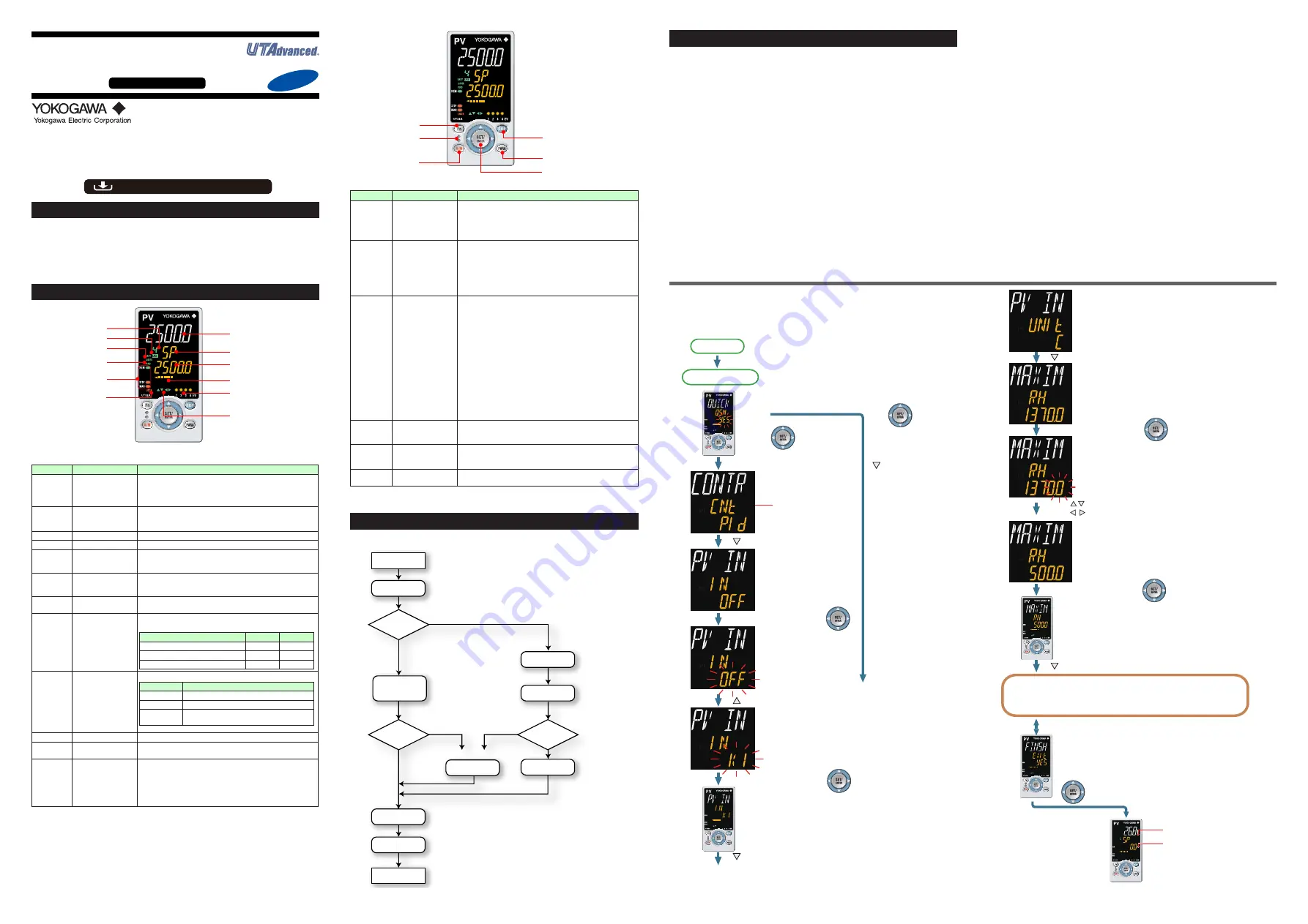
■
Making Settings Using Quick Setting Function
Example: Setting to PID control, thermocouple type K (range of 0.0 to
500.0
0
C), and current control output
For the detailed procedure and switching of displays, see "Flow of Quick Setting
Function" below. For the parameters to set, see the next page.
(1) Press the SET/ENTER key while YES for QSM (Quick setting mode) is displayed.
(2) Set the control type parameter (CNT) to PID (PID control).
(3) Set the PV input type parameter (IN) to K1 (-270.0 to 1370.0
0
C).
(4) Set the PV input unit parameter (UNIT) to C (Degree Celsius).
(5) Set the maximum value of PV input range parameter (RH) to 500.0.
(6) Set the minimum value of PV input range parameter (RL) to 0.0.
(7) Set the output type selection parameter (OT) to OUT terminals (current=00.02).
(8) Set the loop-2 parameter same as above. (LP2 lamp is lit)
(9) Finally, EXIT is displayed. Change NO to YES and press the SET/ENTER key to
complete the setup. Operation Display appears.
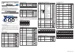
■ Flow of Quick Setting Function
In Quick setting mode, the parameter guide appears on PV display.
This guide can be turned on/off with the Fn key.
1.
2.
3.
4.
5.
6.
7.
8.
9.
10.
11.
12.
Follow the same procedure to set RL to 0.0 and OT to 00.02.
Next, set the Loop-2 parameters in the same manner as the Loop-1 parameters.
If the Loop-2 parameters are shown, the LP2 lamp lights.
Set other parameters as needed.
Press the SET/ENTER key while YES
is displayed to start the Quick setting.
[NO]
Select NO with the Down
arrow key and press the
SET/ENTER key.
Select NO to return to
the Operation Display.
Power-on
First, the loop-1 control
type parameter (CNT) is
displayed.
Initial value: PID (PID control)
Press the Down arrow key.
The loop-1 PV input
type parameter (IN) is
displayed.
Initial value: OFF
Press the SET/ENTER key.
OFF blinks.
Blinking allows you to
change the setting.
Press the Up arrow key.
K1 is displayed.
K1 has been registered.
Press the SET/ENTER key.
Press the Down arrow key.
[YES]
Quick setting starts
The last digit of the upper limit value blinks.
The parameter RH (maximum value of
PV input range for loop-1) has been
changed to 500.0.
The setpoint for the parameter RH has been registered.
Press the Down arrow key.
Operation Display
The loop-1 PV input unit parameter
(UNIT) is displayed.
Initial value: C (Degree Celsius)
Press the Down arrow key.
Displays the measured
input value (PV).
Displays the target
setpoint (SP).
Finally, EXIT is displayed.
Press the SET/ENTER key to swtich to the setting mode.
Change NO to YES and press the SET/ENTER key
to complete the setup of the basic function.
Operation Display appears.
The Quick setting function continues in the NO state.
Press the SET/ENTER key.
Press the SET/ENTER key.
The upper limit value of the setting
range for loop-1 is displayed for the
parameter RH (maximum value of
PV input range).
Change the setpoint using the Up/Down
arrow keys
to increase and decrease the value and
the Left/Right arrow keys to move
between digits.


