
IM 05P08D31-11EN page 6/12
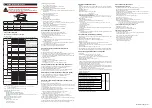
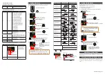
■ Parameters to be set
Control Type (Loop-1/Loop-2)
Parameter Symbol Name of Parameter
Setting Range
CNT
Control type
PID: PID control
ONOF: ON/OFF control (1 point of hysteresis)
ONOF2: ON/OFF control (2 points of hysteresis)
Note: Some setpoints may not be displayed depending on the model and suffix codes.
Input Function (Loop-1/Loop-2)
Parameter Symbol Name of Parameter
Setting Range
IN
PV input type
OFF: Disable (displayed for loop-1 only)
K1: -270.0 to 1370.0
0
C / -450.0 to 2500.0
0
F
K2: -270.0 to 1000.0
0
C / -450.0 to 2300.0
0
F
K3: -200.0 to 500.0
0
C / -200.0 to 1000.0
0
F
J: -200.0 to 1200.0
0
C / -300.0 to 2300.0
0
F
T1: -270.0 to 400.0
0
C / -450.0 to 750.0
0
F
T2: 0.0 to 400.0
0
C / -200.0 to 750.0
0
F
B: 0.0 to 1800.0
0
C / 32 to 3300
0
F
S: 0.0 to 1700.0
0
C / 32 to 3100
0
F
R: 0.0 to 1700.0
0
C / 32 to 3100
0
F
N: -200.0 to 1300.0
0
C / -300.0 to 2400.0
0
F
E: -270.0 to 1000.0
0
C / -450.0 to 1800.0
0
F
L: -200.0 to 900.0
0
C / -300.0 to 1600.0
0
F
U1: -200.0 to 400.0
0
C / -300.0 to 750.0
0
F
U2: 0.0 to 400.0
0
C / -200.0 to 1000.0
0
F
W: 0.0 to 2300.0
0
C / 32 to 4200
0
F
PL2: 0.0 to 1390.0
0
C / 32.0 to 2500.0
0
F
P2040: 0.0 to 1900.0
0
C / 32 to 3400
0
F
WRE: 0.0 to 2000.0
0
C / 32 to 3600
0
F
JPT1: -200.0 to 500.0
0
C / -300.0 to 1000.0
0
F
JPT2: -150.00 to 150.00
0
C / -200.0 to 300.0
0
F
PT1: -200.0 to 850.0
0
C / -300.0 to 1560.0
0
F
PT2: -200.0 to 500.0
0
C / -300.0 to 1000.0
0
F
PT3: -150.00 to 150.00
0
C / -200.0 to 300.0
0
F
0.4-2V: 0.400 to 2.000 V
1-5V: 1.000 to 5.000 V
4-20: 4.00 to 20.00 mA
0-2V: 0.000 to 2.000 V
0-10V: 0.00 to 10.00 V
0-20: 0.00 to 20.00 mA
-1020: -10.00 to 20.00 mV
0-100: 0.0 to 100.0 mV
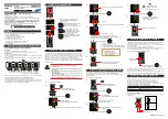
UNIT
PV input unit
-: No unit, C: Degree Celsius
-: No unit, - -: No unit, - - -: No unit, F: Degree Fahrenheit
RH
Maximum value of
PV input range
Depends on the input type.
- For temperature input -
Set the temperature range that is actually controlled.
(RL<RH)
- For voltage / current input -
Set the range of a voltage / current signal that is applied.
The scale across which the voltage / current signal is
actually controlled should be set using the maximum value
of input scale (SH) and minimum value of input scale (SL).
(Input is always 0% when RL = RH.)
RL
Minimum value of
PV input range
SDP
PV input scale
decimal point
position
0: No decimal place
1: One decimal place
2: Two decimal places
3: Three decimal places
4: Four decimal places
SH
Maximum value of
PV input scale
-19999 to 30000, (SL<SH), | SH - SL | ≤ 30000
SL
Minimum value of
PV input scale
Note 1: SDP, SH, and SL are displayed only for voltage/current input.
Note 2: W: W-5%Re/W-26%Re (Hoskins Mfg.Co.), ASTM E988
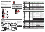
Output Function (Loop-1/Loop-2)
Parameter Symbol
Name of Parameter
Setting Range
OT
Output type selection
Output type
00
Lit when the loop-2
parameter is displayed
Symbol
The LP2 lamp is lit while the output type
selection parameter for loop-2 is displayed.
00: OFF
01: OUT terminals (voltage pulse)
02: OUT terminals (current)
03: OUT terminals (relay)
06: OUT2 terminals (relay)
07: OUT2 terminals (voltage pulse)
08: OUT2 terminals (current)
CT
Control output cycle time
The LP2 lamp is lit while the control output
cycle time parameter for loop-2 is displayed.
0.5 to 1000.0 s
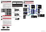
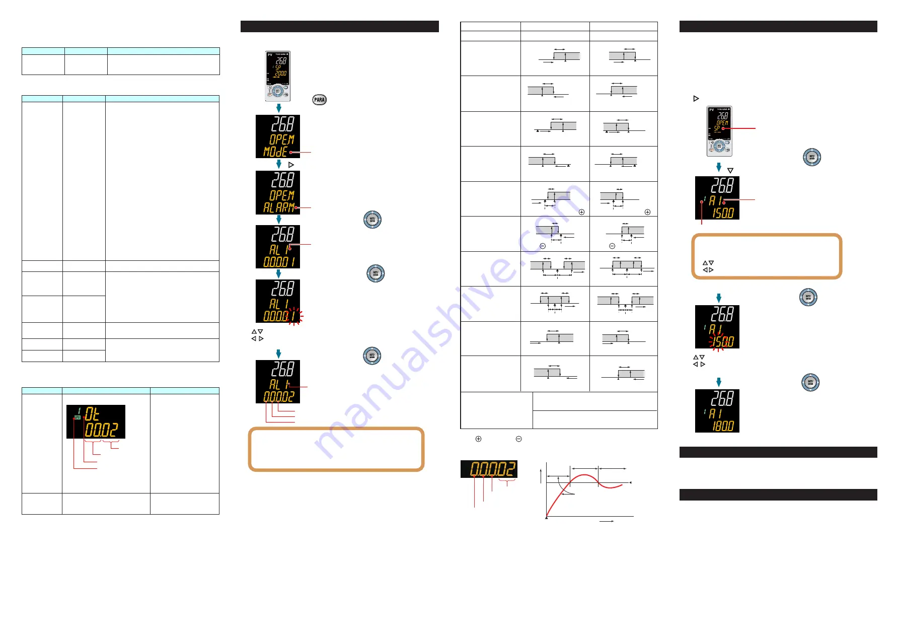
4. Setting Alarm Type
The following operating procedure shows an example of changing the alarm-1 type
(factory default: PV high limit alarm) to PV low limit alarm (setpoint: 02).
1.
2.
3.
4.
5.
6.
MODE menu is displayed.
Press the SET/ENTER key.
Press the SET/ENTER key.
Hold down the key for 3 seconds.
Show the Operation Display.
ALRM menu is displayed.
Press the SET/ENTER key.
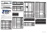
Energized/De-energized
Latch action
Stand-by action
Symbol
●
To change the alarm type, change the last 2 digits of the
5-digit value.
●
Stand-by action and excitation are turned on or off by
selecting 1 or 0. (See “ Setting Display of Alarm Type.”)
●
For the latch action, see User ’s Manual (IM 05P08D31-01EN).
The parameter AL1 (alarm-1 type) is
displayed.
The last digit of the setpoint blinks.
Change the setpoint using the Up/Down arrow keys
to increase and decrease the value and
the Left/Right arrow keys to move between digits.
Press the Right arrow key until
ALRM menu appears.
The alarm-1 type setpoint 02 (PV
low limit)
is registered.
After the setup is completed, press
the DISP key once to return to the
Operation Display.
Hysteresis
Alarm setpoint
PV
SP or Target SP
Hysteresis
PV
Deviation setpoint
SP or Target SP
Deviation
setpoint
PV
Hysteresis Hysteresis
Open
(
unlit
)
Closed
(lit)
SP or Target SP
PV
Deviation setpoint
Hysteresis
-
-
SP or Target SP
PV
Hysteresis Hysteresis
Deviation
setpoint
Open
(
unlit
)
SP or
Target SP
Alarm setpoint
Hysteresis
SP or
Target SP
Hysteresis
Alarm setpoint
Alarm setpoint
Output
Hysteresis
Closed
(lit)
Hysteresis
Alarm setpoint Output
Alarm setpoint
Hysteresis
PV
Hysteresis
Alarm setpoint
PV
SP or Target SP
Hysteresis
PV
Deviation setpoint
SP or Target SP
Deviation
setpoint
PV
Hysteresis Hysteresis
SP or Target SP
PV
Deviation setpoint
Hysteresis
SP or Target SP
PV
Hysteresis Hysteresis
Deviation
setpoint
Closed
(unlit)
SP or
Target SP
Alarm setpoint
Hysteresis
SP or
Target SP
Hysteresis
Alarm setpoint
Alarm setpoint
Hysteresis
PV
Alarm setpoint
Output
Hysteresis
Hysteresis
Alarm setpoint Output
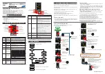
No alarm (00)
Alarm Action (De-energized)
PV high limit (01)
Analog input PV high limit (19)
Analog input PV2 high limit (21)
PV low limit (02)
Analog input PV low limit (20)
Analog input PV2 low limit (22)
SP high limit (03)
Target SP high limit (09)
SP low limit (04)
Target SP low limit (10)
Deviation high limit (05)
Target SP deviation high
limit (11)
Deviation low limit (06)
Target SP deviation low limit (12)
Deviation high and low
limits (07)
Target SP deviation high and
low limits (13)
Deviation within high and low
limits (08)
Target SP deviation within high
and low limits (14)
Control output high limit (15)
Control output low limit (16)
PV velocity (29)
Fault diagnosis alarm (30)
FAIL (31)
Alarm Type (Alarm Setpoint)
Alarm Action (Energized)
Open
(
unlit
)
Open
(
unlit
)
Open
(
lit
)
Closed
(lit)
Open
(
unlit
)
Open
(
lit
)
Closed
(unlit)
Closed
(unlit)
Open
(
lit
)
Closed
(unlit)
Closed
(unlit)
Open
(
lit
)
Open
(
lit
)
Closed
(lit)
Closed
(lit)
Closed
(lit)
Closed
(lit)
Closed
(lit)
Closed
(lit)
Closed
(lit)
Closed
(lit)
Open
(
unlit
)
Open
(
unlit
)
Open
(
unlit
)
Open
(
unlit
)
Open
(
unlit
)
Open
(un
lit
)
Open
(
lit
)
Open
(
lit
)
Open
(
lit
)
Open
(
lit
)
Open
(
lit
)
Open
(
lit
)
Closed
(unlit)
Closed
(unlit)
Closed
(unlit)
Closed
(unlit)
Closed
(unlit)
Closed
(unlit)
Burnout of PV input, ADC failure, RJC error.
For the factory default, the contact output is turned ON in normal operation,
OFF at the time of FAIL. Control output: OFF or 0%, Alarm output: OFF
Note 1: “Open/closed” shows status of relay contact, and “lit/unlit” shows status of EV (event) lamp.
Note 2: Positive setpoint, Negative setpoint
Setting Display of Alarm Type
Stand-by Action
Energized (0) / De-energized (1)
Alarm type
Without (0) or With (1)
Stand-by action
Latch action (0/1/2/3/4)
See
User’s
Manual (IM 05P08D31-01EN).
PV low limit
alarm setpoint
Treated
as normal
ºC
Power-on
Time
The alarm output does not turn on
in this region even if the PV valule
is below PV low limit alarm setpoint.
Normal
Abnormal
The alarm output
turns on.
6. Setting Alarm Setpoint
The following operating procedure shows an example of setting the alarm-1 setpoint
of group 1 to 180.0.
Before setting the alarm setpoint, check the alarm type.
To change the alarm type, see “5. Setting Alarm Type.”
1.
2.
3.
4.
5.
6.
Press the Right arrow key.
Press the SET/ENTER key.
SP menu is displayed.
Display the parameter and group that need to be changed.
Blinks during the change.
Press the SET/ENTER key.
Press the Down arrow key until A1 appears.
Press the SET/ENTER key.
Show the Operation Display.
Display MODE menu with the same procedure as described in
Setting Alarm Type.
Group
The parameter A1 is displayed.
A1 to A4 represent the alarm-1 to -4 setpoints.
Each parameter and group can be changed
in the Parameter Setting Displays of alarms
using arrow keys.
Up/Down arrow keys: parameters
Left/Right arrow keys: groups
Change the setpoint using the Up/Down arrow
keys to increase and decrease the value and
the Left/Right arrow keys to move between digits.
The setpoint has been registered.
After the setup is completed, press
the DISP key once to return to the
Operation Display.
Initializing parameter values
Parameters that you have changed can be initialized to factory default values or user
default values. For details, see “Parameter Initialization” in the User’s Manual (IM
05P08D31-01EN).
Changing the parameter display levels
This operation guide does not explain all the parameters. To display all the param-
eters, you need to change the parameter display level to professional setting mode.
For details, see “Setting Security Functions” in the User’s Manual (IM 05P08D31-
01EN).


