
IM 05P08D31-11EN page 8/12
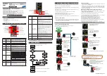
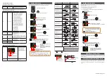
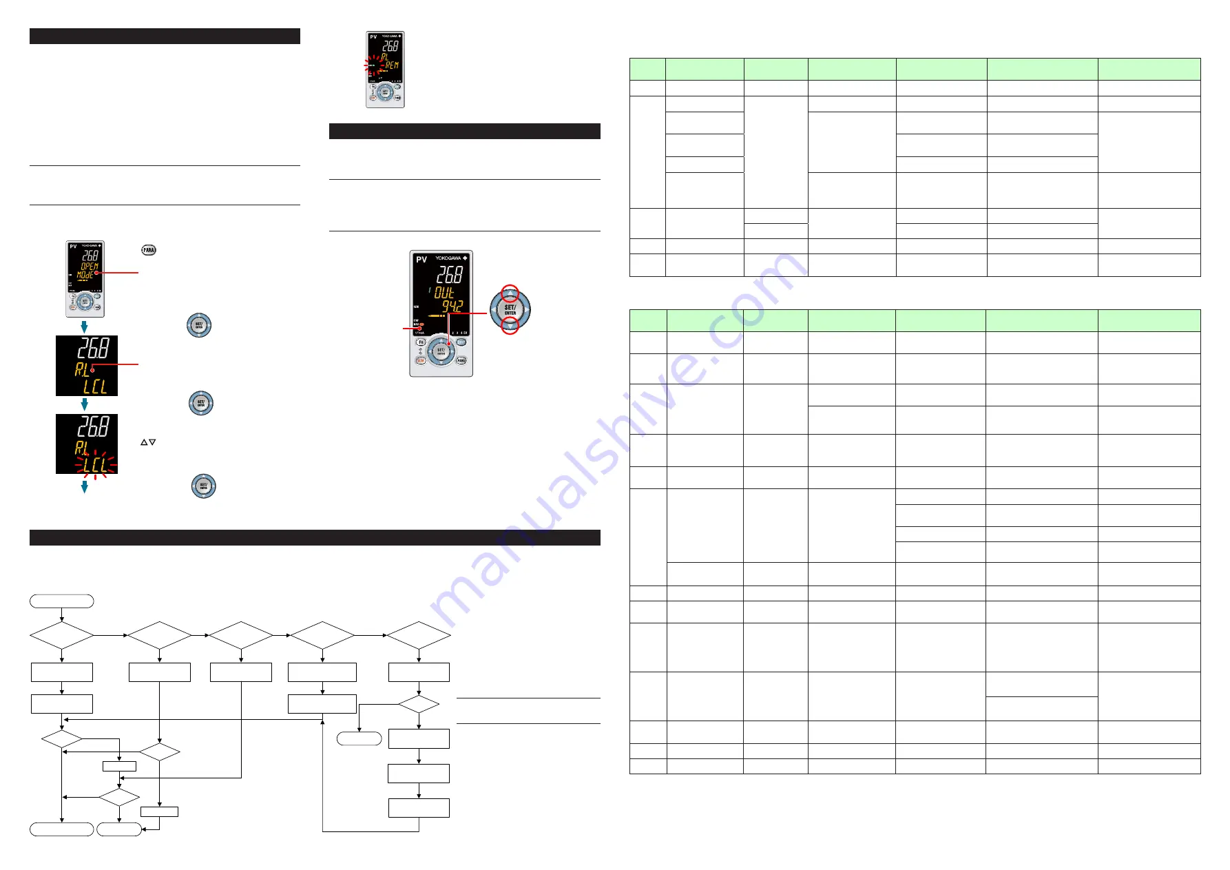
7. Switching between REM (Remote) and LCL (Local)
Remote and local switching can be performed using any of the following:
(1) Contact input, (2) Parameter, (3) Communication, and (4) User function key.
LCL (Local)
Control is performed using the target setpoint set on the controller.
REM (Remote)
Control is performed using a setpoint via communication for the target setpoint. The
following shows an example of switching from local to remote using the parameter.
(Only in cases where the communication is specified.)
For details of other switching methods, see User’s Manual (IM 05P08D31-01EN).
• The PID group for the local SP number is used as PID in remote mode.
NOTE
When the contact input is ON, operation cannot be performed using the parameter,
communication, or key. When the contact input is OFF and the setting is switched
using the parameter, communication, or key, the last switching operation is per-
formed.
1.
2.
3.
4.
5.
Show the Operation Display.
Hold down the PARA key
for 3 seconds to display MODE menu.
Press the SET/ENTER key.
Press the SET/ENTER key.
The REM lamp is lit.
Change the operation mode using
the Up/Down arrow keys.
Blinks during the change.
Press the SET/ENTER key.
The parameter R.L (REMOTE/LOCAL switch)
is displayed.
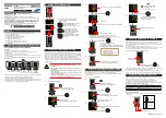
8. Manipulating Control Output in Manual Mode
This is an example of operating the Loop-1 control output. To operate the Loop-2
control output, use the OUT Display showing the LP2 lamp.
NOTE
In manual mode, control output is manipulated by operating the keys (the value is
changed using the Up/Down arrow keys, then outputted as it is).
Even if the SET/ENTER key is not pressed, the control output value changes ac-
cording to the displayed value.
In stop mode (when the STOP lamp is lit), control output cannot be manipulated.
MAN lamp is lit.
Up arrow key:
increases control output.
Down arrow key:
decreases control output.
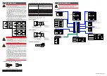
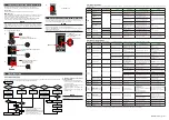
9. Troubleshooting
■ Troubleshooting Flow
If the Operation Display does not appear after turning on the controller’s power, check the procedures in the following flowchart.
If a problem appears to be complicated, contact our sales representatives.
Is the controller
defective?
Contact us for repair. Problem solved.
No communication
capability
Completely
inactive?
Yes
Yes
Yes
No
No
No
Key
operation
failure?
Yes
No
Yes
Check wiring of the
power terminals.
Check the key lock
setting.
Display
failure?
*
Yes
No
Turn off power, and
then turn it on again.
I/O signal
failure?
Yes
No
Check the
supply voltage.
Check the
specifications and polarity
of connected devices .
Check the communication-
related parameters.
Check the specifications
of communication
devices.
Check the
communication wiring.
Communication
failure?
No
With
communi-
cation?
Yes
Yes
Normal?
Is the
key locked?
Check the specifications
of the controller.
Yes
No
Correct?
Correct the error(s).
Cancel the setting.
Check the I/O specifications
of the controller.
* The LCD (a liquid crystal display) is used for
a display portion of this product.
The LCD has a characteristic that the display action
becomes late at the low temperature.
Additionally, the luminance and contrast degradation
are caused due to aged deterioration.
However, the control function is not affected.
■
Remedies if Power Failure Occurs
during Operations
• Instantaneous power failure within 20 ms.
A power failure is not detected. Normal
operation continues.
• Power failure for less than about 5 seconds,
or for about 5 seconds or more.
Affects the "settings" and "operation sta-
tus."
For details, see User's Manual (IM
05P08D31-01EN).
NOTE
Write down the settings of parameters for a
repair request.
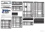
■
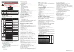
Errors at Power On
The errors shown below may occur in the fault diagnosis when the power is turned on. (For details of Setpoint display and input/output action when each error occurs, see User’s Manual (IM
05P08D31-01EN).)
PV display
(Operation
Display)
Setpoint display
(Operation Display)
Status indicator
(Operation Display)
Parameter that displays error
details
Error description
Cause and diagnosis
Remedy
Indication off Indication off
—
—
Faulty MCU RAM / MCU ROM
MCU RAM / MCU ROM are failed.
Faulty.
Contact us for repair.
ERR
SYS - - - - -
—
—
System data error
System data is corrupted.
Faulty.
Contact us for repair.
PAR 0004
(for user default value error
only)
Setup parameter (PA.ER)
User (parameter) default value
error
User parameter is corrupted.
Initialized to factory default value.
Check and reconfigure the initialized
setting parameters. Error indication is
erased when the power is turned on
again.
PAR 0010
(for setup parameter error
only)
Setup parameter error
Setup parameter data is corrupted.
Initialized to user default value.
PAR 0020
(for operation parameter error only)
Operation parameter error
Operation parameter data is corrupted.
Initialized to user default value.
SLOT 0001
(0001: Error occurs to all
hardware of E1-terminal
areas.)
Setup parameter (OP.ER)
Nonresponding hardware of
extended function (E1-terminal
areas)
Inconsistence of system data and
hardware of extended function.
Nonresponding communication between
hardware of extended function (E1-terminal
areas).
Faulty.
Contact us for repair.
Normal
indication
Normal indication
Rightmost decimal point
on PV display blinks.
Setup parameter (PA.ER)
Calibration value error
Initialized to calibrated default value because
of corrupted factory default value.
Faulty.
Contact us for repair.
Rightmost decimal point
on Symbol display blinks.
Faulty FRAM
Data writing (storing) to FRAM is impossible.
Normal
indication
Normal indication
LADDER lamp blinks
Setup parameter (LA.ER)
Corrupted ladder program
Ladder program is corrupted.
Operates without ladder program.
Download the ladder program again.
Normal
indication
0.000 00000
(Decimal point on the left of
the Symbol display blinks)
—
Setup parameter (OP.ER)
User profile error
User profile is corrupted.
Download the user profile again.
■
Errors during Operation
The errors shown below may occur during operation. (For input/output action when each error occurs, see User’s Manual (IM 05P08D31-01EN).)
PV display
(Operation
Display)
Setpoint display
(Operation Display)
Status indicator
(Operation Display)
Parameter that displays
error details
Error description
Cause and diagnosis
Remedy
AD.ERR
Normal indication (Note)
—
Setup parameter (AD1.E)
Analog input terminal ADC error
•PV input
•PV2 input (E1-terminal area)
Analog input terminal AD value error
Faulty.
Contact us for repair.
RJC.E
(Displays RJC.
E and PV
alternately.)
Normal indication (Note)
—
Setup parameter (AD1.E)
Universal input terminal RJC error
•PV input
•PV2 input (E1-terminal area)
Universal input terminal RJC error
Faulty.
Contact us for repair.
Set the parameter RJC to OFF to erase
error indication.
B.OUT
Normal indication (Note)
—
Setup parameter (AD1.E)
Analog input terminal burnout error
•PV input
•PV2 input (E1-terminal area)
Analog input terminal sensor burnout
Check wiring and sensor.
Error indication is erased in normal
operation.
Setup parameter (PV1.E)
PV input burnout error
(Loop-1, Loop-2)
Burnout of analog input connected to PV
Check wiring and sensor of connected
analog input terminals.
Error indication is erased in normal
operation.
OVER
-OVER
Normal indication
—
Setup parameter (PV1.E)
PV input over-scale
PV input under-scale
(PV values out of -5 to 105%)
(Loop-1, Loop-2)
PV input is out of -5 to 105%. Also occurs
when the data out of range which is the
ladder calculation result is input.
Check analog input value or ladder
program.
Normal
indication
OUT - - - - -
—
Setup parameter (AD2.E)
Feedback input resistor/current
burnout
Feedback input burnout
Check wiring of feedback input resistor/
current. Error indication is erased in
normal operation.
Normal
indication
Normal indication
LADDER lamp blinks
Setup parameter (LA.ER)
Ladder calculation overflow
Floating point computation for ladder
calculation is infinite.
Check the ladder program.
Load factor over 100%
Computation does not end within the
control period (load factor is 100% or
more).
Change the control period or reduce
the number of steps for the ladder
program.
Load factor over 200%
(Forced end)
Computation does not end within the control
period (load factor is 200% or more).
Change the control period or reduce the
number of steps for the ladder program.
Ladder program error
Ladder program is corrupted.
Download the ladder program again. If
the error indication is still not erased,
there is a fault. Contact us for repair.
0.000 00000
(Decimal point on the left of
the Symbol display blinks)
—
Setup parameter (OP.ER)
Peer-to-peer communication error Peer-to-peer communication error
Check that the target devices are
connected correctly.
Recovery at normal receipt.
AT.E
Normal indication
—
Setup parameter (PV1.E)
Auto-tuning time-out
(Loop-1, Loop-2)
Auto-tuning does not end even when 24
hours have elapsed after the start of tuning.
Check the process. Hold down any key to
erase the error indication
VAT.E
Normal indication
—
Setup parameter (AD2.E)
Valve position automatic
adjustment error
Fully-closed valve position is equal to or larger
than the fully-open valve position after automatic
valve position adjustment is performed.
Check wiring and valve. Hold down any
key to erase the error indication.
Normal
indication
0.000 00000
(Decimal point on the left of
the Symbol display blinks)
—
Setup parameter (OP.ER)
Communication error
(RS-485 communication)
Framing parity error
Buffer overflow
Inter-character time-out
Checksum error (PC link communication with
checksum)
CRC check error (Modbus/RTU)
LRC check error (Modbus/ASCII)
Check the communication parameters.
Recovery at normal receipt.
Hold down any key to stop blinking.
Normal
indication
0.000 00000
(Decimal point on the left of
the Symbol display blinks)
—
Setup parameter (OP.ER)
Communication error
(coordinated operation)
Inconsistence of loop between coordinated
master and slaves
Check the communication parameters.
Recovery at normal receipt. Change from remote
to local mode to stop blinking.
When the mode is changed from remote to
local, SP tracking does not work even if it is
set to ON.
Communication from coordinated master is
interrupted for 2 seconds.
Normal
indication
0.000 00000
(Decimal point on the left of
the Symbol display blinks)
—
Setup parameter (OP.ER)
User profile error
User profile is corrupted.
Download the user profile again.
Normal
indication
Normal indication
Rightmost decimal point on
Symbol display blinks.
Setup parameter (PA.ER)
Faulty FRAM
Writing (storing) data to FRAM is impossible. Faulty. Contact us for repair.
Undefined
Undefined
—
—
Faulty MCU / DCU
(ROM / RAM error, corrupted)
MCU / DCU is corrupted.
Faulty. Contact us for repair.
Note: When an error occurs in input shown in Analog input display (Operation display), Setpoint display shows the same symbol as the PV display.


