
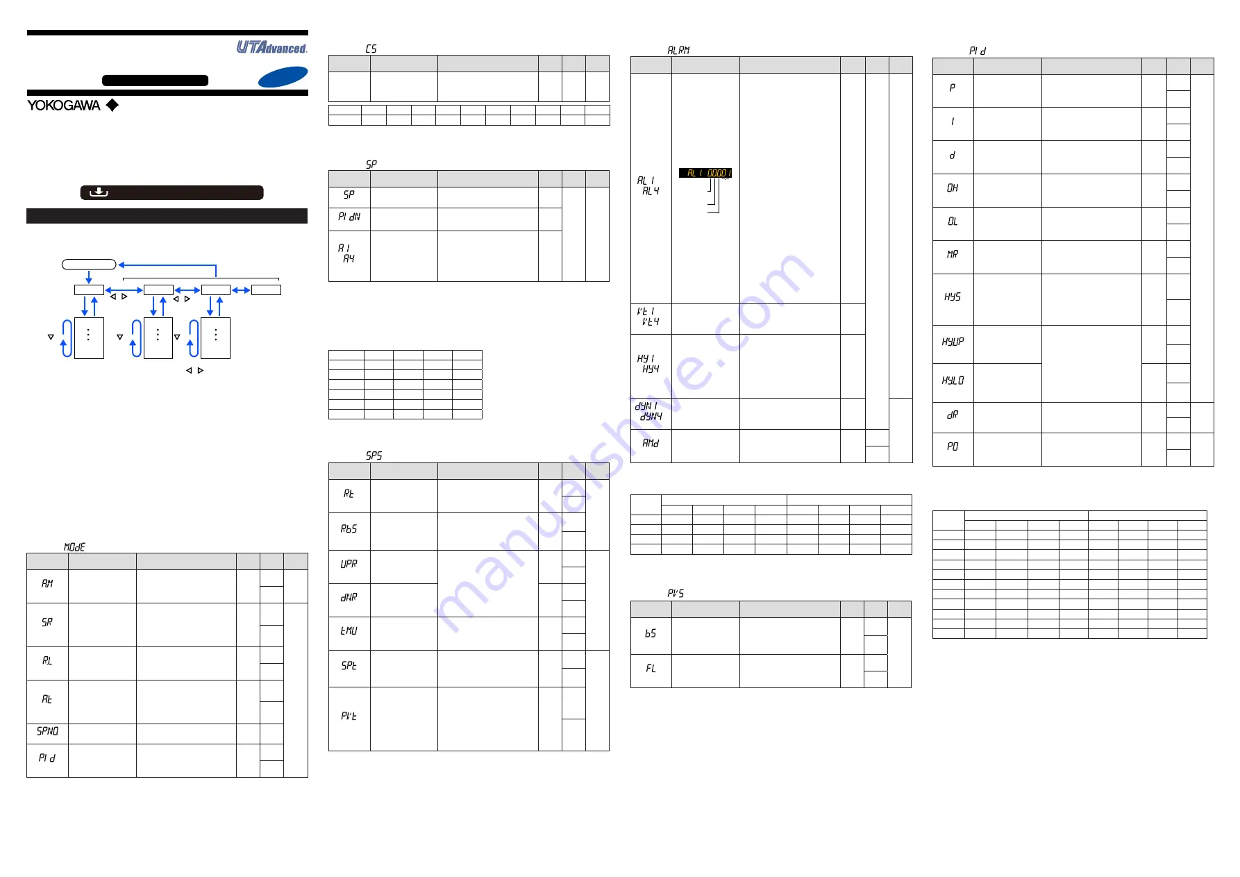
IM 05P08D31-11EN page 9/12
Operation Parameters
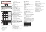
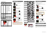
Hold down the PARA key for 3 seconds to move from the Operation Display to the Op-
eration Parameter Setting Display. Press the DISP key once to return to the Operation
Display.
Menu
Hold down PARA key for 3 sec.
DISP key
SET/ENTER key
PARA key
key
key
key
key
key
The parameter groups can be switched using , keys.
Operation Dsipaly
Parameter
Parameter
Parameter
Parameter
Parameter
Parameter
END
Menu
END
Menu
END
END
Menu Display and
Parameter Setting
Display are changed
in a circular pattern.
Move to the Setup Parameter Setting Display:
Hold down the PARA key and the Left arrow key simultaneously for 3 sec.
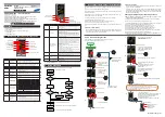
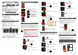
Operation for Setting
· To select the parameter setting displayed as the initial value, press the Down arrow
key to move to the next parameter.
· To change and set the parameter setting, press the SET/ENTER key to start the set-
point blinking. The blinking state allows you to make changes (setting mode). Use the
Up/Down/Left/Right arrow keys to change the setpoint. Press the SET/ENTER key to
register the setting.
Note that there are some parameters which are not displayed depending on the model
and suffix codes, control type (CNT), etc. The parameters for professional setting mode
(LEVL: PRO) are not described in this manual. See User’s Manual (IM 05P08D31-
01EN).
(LP1): Loop-1, (LP2): Loop-2
■
Operation Mode
Menu symbol:
(MODE)
Parameter
symbol
Name of Parameter
Setting Range
Initial
value
User
setting
Display
level
(A.M)
AUTO/MAN switch
AUTO: Automatic mode
MAN: Manual mode
MAN
(LP1)
(LP2)
(S.R)
STOP/RUN switch
STOP: Stop mode
RUN: Run mode
Preset output (PO) is generated in
STOP mode.
Default: Not displayed. STOP/RUN
switch is assigned to contact input.
RUN
(LP1)
EASY
(LP2)
(R.L)
REMOTE/LOCAL switch
LCL: Local mode
REM: Remote mode
(Displayed only in cases where the
communication is specified.)
LCL
(LP1)
(LP2)
(AT)
AUTO-tuning switch
OFF: Disable
1 to 4: Perform auto-tuning. Tuning
result is stored in the specified num-
bered PID.
R: Tuning result is stored in the PID
for reference deviation.
OFF
(LP1)
(LP2)
(SPNO.)
SP number selection
1 to 4 (Depends on the setup param-
eter SPGR. setting.)
1
(PID)
PID number
The PID group number being selected
is displayed.
1 to 4, R: PID group for reference
deviation
1
(LP1)
(LP2)
■
SELECT Parameter
Menu symbol:
(CS)
Parameter
symbol
Name of Parameter
Setting Range
Initial
value
User
setting
Display
level
Registered
parameter
symbol
SELECT parameter 10
to 19
Setting range of a registered parame-
ter.
For details, see User's Manual (IM
05P08D31-01EN).
—
Table
below
EASY
Parameter
n=10
n=11
n=12
n=13
n=14
n=15
n=16
n=17
n=18
n=19
CSn
For the registration of SELECT parameters, see User's Manual (IM 05P08D31-01EN).
■
SP and Alarm Setpoint Setting Parameter
Menu symbol:
(SP)
Parameter
symbol
Name of Parameter
Setting Range
Initial
value
User
setting
Display
level
(SP)
Target setpoint
0.0 to 100.0% of PV input range (EU)
(Setting range: SPL to SPH)
SPL
Table
below
EASY
(PIDN)
PID number selection
Set a PID group number to use.
1 to 4 (Depends on the setup param-
eter PIDG. setting.)
1 to 4
to
(A1 to A4)
Alarm-1 to -4 setpoint
Set a display value of setpoint of PV
alarm, SP alarm, deviation alarm,
output alarm, or velocity alarm.
-19999 to 30000 (Set a value within the
input range.)
Decimal point position depends on the
input type
0
For the parameter SP (target setpoint), 4 groups are displayed for the factory default.
The number of groups can be changed by the setup parameter SPGR. (number of SP
groups). For the alarm setpoint parameter, alarm-1 to -4 are displayed for the factory
default. The number of alarms can be changed using the setup parameter ALNO.
(number of alarms). To change the number of SP groups or alarms, see User's Manual
(IM 05P08D31-01EN).
Use the following table to record SP and alarm setpoints.
Parameter
n=1
n=2
n=3
n=4
SP
PIDN
A1
A2
A3
A4
n: group number
■
SP-related Setting Parameter
Menu symbol:
(SPS)
Parameter
symbol
Name of Parameter
Setting Range
Initial
value
User
setting
Display
level
(RT)
Remote input ratio
SP = Remote input x RT + Remote
input bias
0.001 to 9.999
1.000
(LP1)
STD
(LP2)
(RBS)
Remote input bias
-100.0 to 100.0% of PV input range
span (EUS)
0.0 %
of PV
input
range
span
(LP1)
(LP2)
(UPR)
SP ramp-up rate
Used to prevent SP from changing
suddenly.
Set a ramp-up rate or ramp-down rate
per hour or minute. Set a time unit
using the parameter TMU.
OFF, 0.0 + 1 digit to 100.0% of PV
input range span (EUS)
OFF
(LP1)
EASY
(LP2)
(DNR)
SP ramp-down rate
OFF
(LP1)
(LP2)
(TMU)
SP ramp-rate time unit
HOUR: Ramp-up rate or ramp-down
rate per hour
MIN: Ramp-up rate or ramp-down
rate per minute
HOUR
(LP1)
(LP2)
(SPT)
SP tracking selection
Tracking is performed when the mode
changes from Remote to Local. (The
local setpoint keeps track of the
remote setpoint.)
OFF, ON
ON
(LP1)
STD
(LP2)
(PVT)
PV tracking selection
Causes the setpoint to keep track of
the PV so the setpoint automatically
reverts to its original value at a preset
rate of change. The UPR, DNR, and
TMU are used in combination. Oper-
ating conditions: 1) MAN → AUTO, 2)
STOP → AUTO, 3) Power-on, 4) SP
number change, 5) SP change
OFF, ON
OFF
(LP1)
(LP2)
■
Alarm Function Setting Parameter
Menu symbol:
(ALRM)
Parameter
symbol
Name of Parameter
Setting Range
Initial
value
User
setting
Display
level
to
(AL1 to AL4)
Alarm-1 to 4 type
Example: Alarm-1
Stand-by
action
Latch action
Energized/
De-energize
Alarm
type
Set a 5-digit value in the following order.
[Latch action (0/1/2/3/4)] + [Energized
(0) or De-energized (1)] + [Without (0)
or With (1) Stand-by action] + [Alarm
type: 2 digits (see below)]
For latch action, see User's Manual
(IM 05P08D31-01EN).
AL1,
AL3:
Latch
action
(0)
PV high
limit (01)
Without
Stand-
by
action
(0)
Ener-
gized
(0)
AL2,
AL4:
Latch
action
(0)
Ener-
gized
(0)
Without
Stand-
by
action
(0)
PV low
limit (02)
Table
below
EASY
Alarm type: 2 digits
00: Disable
01: PV high limit
02: PV low limit
03: SP high limit
04: SP low limit
05: Deviation high limit
06: Deviation low limit
07: Deviation high and low limits
08: Deviation within high and low limits
09: Target SP high limit
10: Target SP low limit
11: Target SP deviation high limit
12: Target SP deviation low limit
13: Target SP deviation high and low limits
14: Target SP deviation within high
and low limits
15: OUT high limit
16: OUT low limit
19: Analog input PV high limit
20: Analog input PV low limit
21: Analog input PV2 high limit
22: Analog input PV2 low limit
29: PV velocity
30: Fault diagnosis
31: FAIL
to
(VT1 to VT4)
PV velocity alarm time
setpoint 1 to 4
0.01 to 99.59 (minute.second)
1.00
to
(HY1 to HY4)
Alarm-1 to -4 hysteresis
Set a display value of setpoint of
hysteresis.
-19999 to 30000 (Set a value within
the input range.)
Decimal point position depends on
the input type.
When the decimal point position for
the input type is set to "1", the initial
value of the hysteresis is "1.0".
10
to
(DYN1 to DYN4)
Alarm-1 to -4 On-delay
timer
An alarm output is ON when the delay
timer expires after the alarm setpoint
is reached.
0.00 to 99.59 (minute.second)
0.00
STD
(AMD)
Alarm mode
0: Always active
1: Not active in STOP mode
2: Not active in STOP or MAN mode
0
(LP1)
(LP2)
For the alarm function setting parameter, 4 alarms are displayed for the factory default.
The number of alarms can be changed by the setup parameter ALNO. (number of
alarms). To change the number of alarms, see User's Manual (IM 05P08D31-01EN).
Parameter
Loop-1
Loop-2
n=1
n=2
n=3
n=4
n=1
n=2
n=3
n=4
ALn
VTn
HYn
DYNn
n: alarm number
■
PV-related Setting Parameter
Menu symbol:
(PVS)
Parameter
symbol
Name of Parameter
Setting Range
Initial
value
User
setting
Display
level
(BS)
PV input bias
-100.0 to 100.0% of PV input range
span (EUS)
0.0 %
of PV
input
range
span
(LP1)
EASY
(LP2)
(FL)
PV input filter
OFF, 1 to 120 s
OFF
(LP1)
(LP2)
■
PID Setting Parameter
Menu symbol:
(PID)
Parameter
symbol
Name of Parameter
Setting Range
Initial
value
User
setting
Display
level
(P)
Proportional band
0.0 to 999.9%
When 0.0% is set, it operates as
0.1%.
5.0%
(LP1)
EASY
(LP2)
(I)
Integral time
OFF: Disable
1 to 6000 s
240 s
(LP1)
(LP2)
(D)
Derivative time
OFF: Disable
1 to 6000 s
60 s
(LP1)
(LP2)
(OH)
Control output high limit -4.9 to 105.0%, (OL<OH)
100.0%
(LP1)
(LP2)
(OL)
Control output low limit
-5.0 to 104.9%, (OL<OH), SD: Tight
shut
0.0%
(LP1)
(LP2)
(MR)
Manual reset
Enabled when integral time is OFF.
The manual reset value equals the
output value when PV = SP.
-5.0 to 105.0%
50.0%
(LP1)
(LP2)
(HYS)
Hysteresis (in ON/OFF
control)
In ON/OFF control: 0.0 to 100.0% of
PV input range span (EUS)
In
ON/OFF-
control:
0.5 % of
PV input
range
span
(LP1)
(LP2)
(HY.UP)
Upper-side hysteresis
(in ON/OFF control)
0.0 to 100.0% of PV input range
span (EUS)
0.5 %
of PV
input
range
span
(LP1)
(LP2)
(HY.LO)
Lower-side hysteresis
(in ON/OFF control)
0.5 %
of PV
input
range
span
(LP1)
(LP2)
(DR)
Direct/reverse action
switch
RVS: Reverse action
DIR: Direct action
RVS
(LP1)
STD
(LP2)
(PO)
Preset output
In STOP mode, fixed control output
can be generated.
0.0%
(LP1)
EASY
(LP2)
For the PID setting parameter, 4 groups are displayed for the factory default.
The number of groups can be changed by the setup parameter PIDG. (number of PID
groups). To change the number of PID groups, see User's Manual (IM 05P08D31-
01EN).
If you are using two or more groups of PID parameters, use the following table to record their setting values.
Parameter
Loop-1
Loop-2
n=2
n=3
n=4
R
n=2
n=3
n=4
R
P
I
D
OH
OL
MR
HYS
HY.UP
HY.LO
DR
PO
n: group number
Operation
Guide
UT32A-D
Digital Indicating Controller
(Dual-loop type)
Operation Guide
Yokogawa Electric Corporation
Parameters
For details of the each function, refer to the electronic manual. Manuals can be
downloaded or viewed at the following URL.
Functional
Enhancement
http://www.yokogawa.com/ns/ut/im/
This operation guide describes the functions of parameters briefly. The parameter
symbols listed are in the order shown on the display in each group of menu symbols. In
addition, each parameter table has a “User Setting” column, where you can record your
setpoints when setting them in the controller. The scrolling guide is displayed on PV
display in the Parameter Setting Display. This guide can be turned on/off with the Fn key.
«Standard Code Model»


