<3. INSTALLATION, PIPING, AND WIRING>
3-5
IM 12E04A02-02E
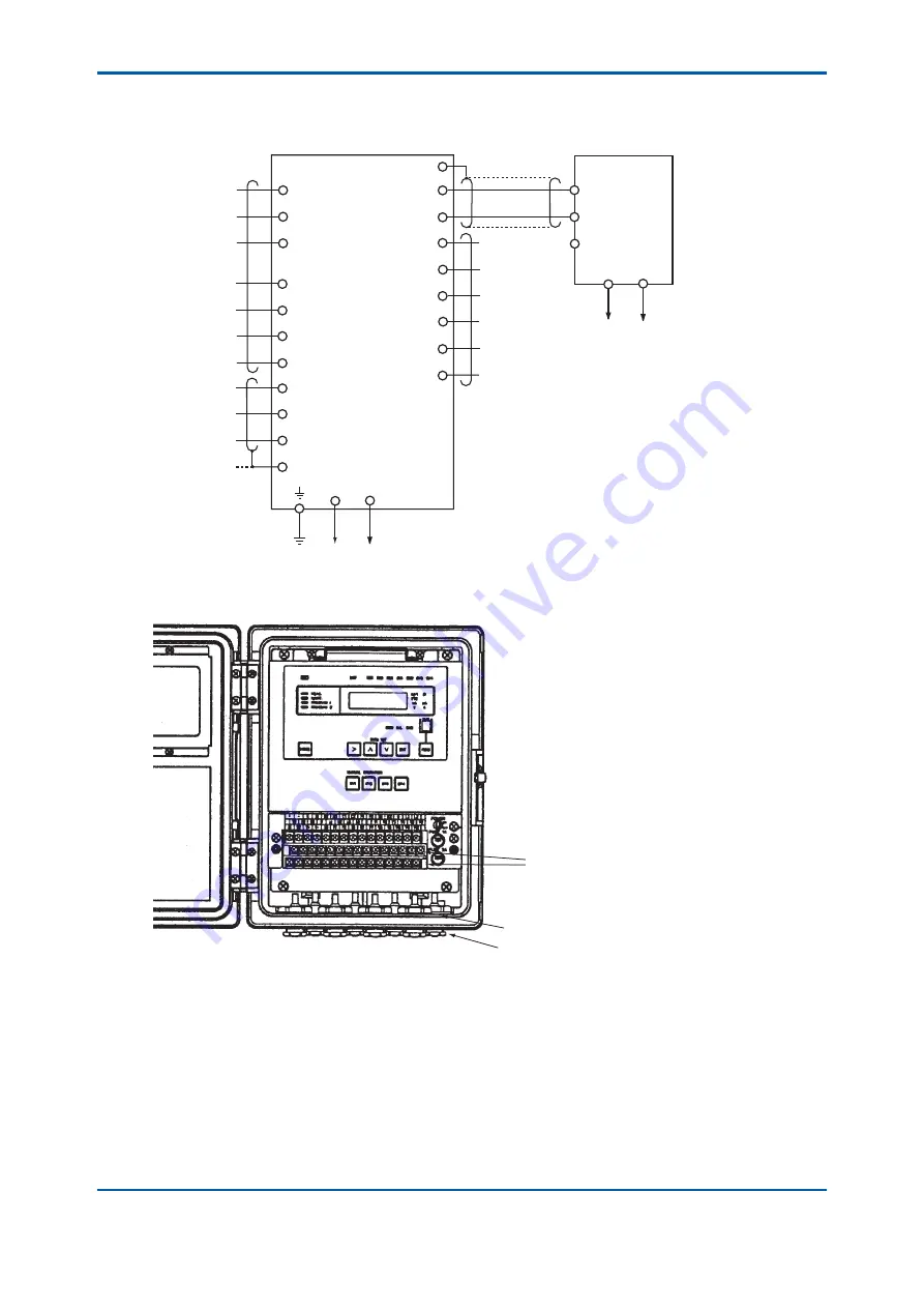
(5) Contact output (maintenance, failure, upper and lower limit alarms, or automatic zero
calibration/cleaning output) wiring (if necessary)
R1
R2
R3
A1
A2
A3
A4
TD
RD
DG
G
REMOTE
RANGE
ANALOG
OUTPUT
+
G
–
M1
M2
F1
F2
C1
C2
Analog output wiring
+
–
G
To power supply
Maintenance
contact output
Failure
contact output
Upper and lower limit alarm
or automatic cleaning and
zero-calibration contact output
Receiving instrument
Turbidity converter
Remote range
selection
contact input
Range contact
output
Digital output
(RS-232C)
POWER
L1
L2
MAINT
FAIL
AUX
F0305.ai
ANSWER
BACK
DIGITAL
OUTPUT
GroundTo power supply
Figure 3.5 External Wiring Diagram
Wiring terminal brock
External wiring cable glands
(5 places)
F0306.ai
Figure 3.6 Converter External Wiring Terminal Block and Cable Connections
Where as the converter has 5 cable inlet ports. As a rule, use one cable for each port.
Note: Be sure to insert cable gland with blind plugs into the unused cable connections.
3rd Edition : May. 31, 2010-00
Summary of Contents for Vigilant Plant EXA TB Series
Page 49: ...Blank Page ...
Page 59: ...Blank Page ...
Page 119: ...Blank Page ...
Page 125: ...Blank Page ...
Page 127: ...Blank Page ...
Page 133: ...Blank Page ...


