<3. INSTALLATION, PIPING, AND WIRING>
3-7
IM 12E04A02-02E
(2) Make the soldered leadwire length almost the same as other conductor lengths and attach
crimp terminal lugs conforming to an M4 (4 mm) screw to the tips of each conductor and this
leadwire.
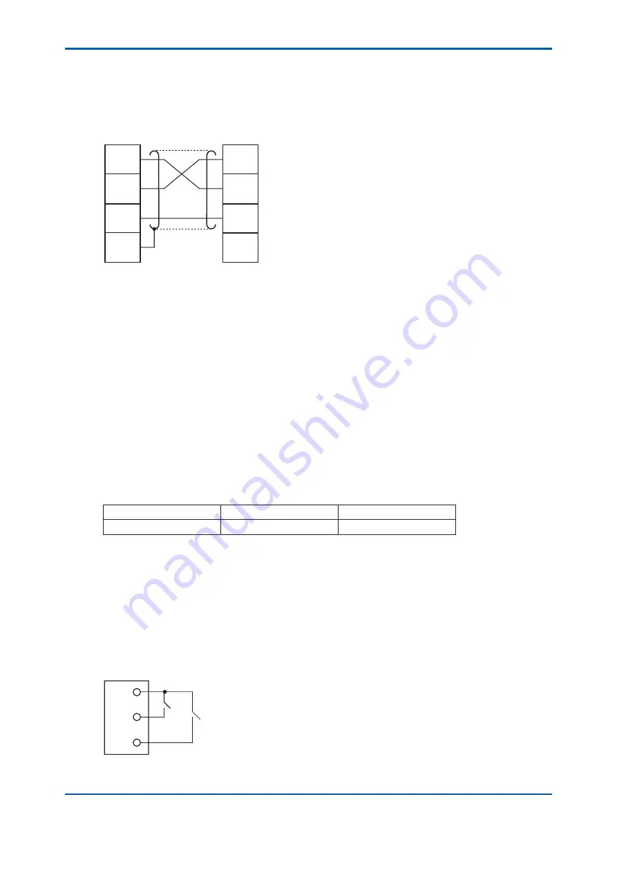
(3) Connect the cable to the converter terminals (TD, RD, DG, and G). Connect the conductors
as shown in Figure 3.7. (Do not ground the shield on the receiving side).
TD
RD
DG
G
TD
RD
DG
G
Converter
Receiving equipment
TM1
Shield
F0307.ai
Figure 3.7 Digital Output Wiring Connection
3.3.4
Contact Input and Contact Output (Range Output)
Wiring
As output ranges, three types of ranges can be set, and output can be obtained by freely
switching these ranges. The output range selection is “remote”, “local” or “auto” mode.
This wiring is applied if the range is changed in “remote” mode (see Section 6.6 (12)) or the range
contact output is used.
Use a 2-conductor cable of
fi
nished OD 6 to 12 mm for the wiring. However, use a 3-conductor
cable when remote range selection only is used and a 4-conductor cable when only range
contact output is used.
The on and off contact statues are identi
fi
ed with the resistance value conditions shown in Table
3.1. In doing wiring, con
fi
rm that a contact meeting these conditions is used.
Table 3.1 On/off Identi
fi
cation of Contact Input for Switching “Remote” Range
On status identi
fi
cation
Off status identi
fi
cation
Resistance value (contact)
200
Ω
or less
100 k
Ω
or more
The cable end-treatment procedure and connection procedure on the converter connection side
are shown below.
(1) Strip off about 40 mm of the cable insulation covering from the end and attach suitable
terminal lugs
fi
tted to M4 (4 mm) screws to the tip of each conductor.
(2) Connect the cable conductors to “remote” range selection terminals R1, R2, and R3 and
range contact output terminals A1, A2, A3 and S4.
“Remote” range switching on/off contact input is performed between terminals R1 and R2, and
between terminals R1 and R3 (See
fi
gure 3.8). The relationship between the on/off contact input
and the output range is as shown in Table 3.2.
R1
R2
R3
F0308.ai
Figure 3.8 Remote Range Switching Contact Input
3rd Edition : May. 31, 2010-00
Summary of Contents for Vigilant Plant EXA TB Series
Page 49: ...Blank Page ...
Page 59: ...Blank Page ...
Page 119: ...Blank Page ...
Page 125: ...Blank Page ...
Page 127: ...Blank Page ...
Page 133: ...Blank Page ...


