background image

8

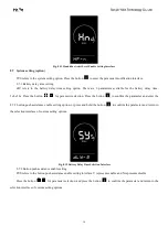
Fig. 6-3 Imperial System Setting Interface

Fig. 6-4 Metric System Setting Interface

7. General parameter setting

The steps for general parameter setting are as follows:
In the power-on state, when the display shows the speed of 0,

(1) Press and hold the buttons

/

at the same time for more than 2 seconds to enter the selection interface of

general setting options;

(2) Press and hold the buttons

and

at the same time for more than 2 seconds to enter the selection interface of

general parameter setting options;

(3) Press the button

/

to switch the function, and press the button

to enter the parameter modification

interface;

(4) Press the button

/

for parameter selection;

(5) Press the button

to save the parameter and enter the next selection interface of general parameter setting

options;

(6) Press and hold the button

to save the parameter and exit the selection interface of general parameter setting

options.

7.1 Wheel diameter setting

Ld refers to the wheel diameter setting option. Available parameters include: 8-26, 700C, 28-30 inches.

Press the button

to enter the parameter modification interface. Press the button

/

to select the wheel

diameter corresponding to your e-bike (to ensure the accuracy of the speed and distance indication of the display). Press the

button

to save the parameter and enter the next selection interface of general parameter setting options.

Summary of Contents for YL80C

Page 1: ...Tianjin Yolin Technology Co Ltd User Manual for E bike Display YL80C ...

Page 2: ...etting 6 6 1 Trip distance reset 6 6 2 Backlight luminance setting 7 6 3 Metric imperial system setting 7 7 General parameter setting 8 7 1 Wheel diameter setting 8 7 2 Speed limit setting 9 8 Custom setting 9 8 1 Battery level setting 11 8 2 Assistance parameter setting option 11 8 3 Current limit setting 12 8 4 Assistance sensor setting option 13 8 5 Speed sensor setting 14 8 6 Handlebar functio...

Page 3: ...11 1 Wiring sequence of standard connector 19 12 Considerations 20 Schedule 1 Error Code Definitions 20 Schedule 2 Assist Level Ratio Default Values 20 ...

Page 4: ...power supply Rated working current 15mA Maximum working current 30mA Leakage current at power off 1uA Working current at the supply controller end 50mA Working temperature 20 60 Storage temperature 30 70 3 Appearance and dimensions Fig 3 1 Picture of Display 80C Fig 3 2 Picture of Display 80C Buttons ...

Page 5: ...dication Error code indicator USB connection indicator reserved Heart rate indicator reserved Bluetooth connection indicator reserved Custom parameter setting e g wheel diameter speed limit battery level assist level power on password controller current limit etc Reset function 4 2 Functional area layout Fig 4 1 Functional Area Layout Interface of Display YL80C Battery level indicator Speed indica...

Page 6: ... off state the display will no longer use the battery power and its leakage current will be less than 1uA If your e bike is not used for more than 10 minutes the display will be automatically powered off 5 2 Display interface After the display is turned on the display will show the real time speed km h and the trip distance km by default By pressing the button the information displayed will be swi...

Page 7: ...rface The push assistance function can only be used when you are pushing your e bike Please do not use it during riding 5 4 Headlight on off By pressing the button the controller will turn on the headlights and the display backlight will turn dark by pressing the button again the controller will turn off the headlights and the display backlight will resumes the luminance Fig 5 3 Backlight on Indic...

Page 8: ...tery level indication 4 segment indication 3 segment indication 2 segment indication 1 segment indication Undervoltage flashing Fig 5 5 Battery Level Indicator Interface 5 7 Motor power indicator The display can indicate the output power of the motor as shown in the figure below Fig 5 6 Motor Power Indicator Interface 5 8 Error code indicator When a fault occurs in the electronic control system of...

Page 9: ...ions and press the button to enter the parameter modification interface 3 Press the button for parameter selection 4 Press the button to save the parameter and return to the selection interface of general setting options 5 Press and hold the button to save the parameter and exit the selection interface of general setting options The following selection interfaces of general setting options are ava...

Page 10: ... Press the button for parameter selection Press the button to save the parameter and return to the selection interface of general setting options Fig 6 2 Backlight Luminance Setting Interface 6 3 Metric imperial system setting Un refers to the metric imperial system setting option U 1 represents the imperial system and U 2 represents the metric system Press the button to enter the parameter modifi...

Page 11: ...r the parameter modification interface 4 Press the button for parameter selection 5 Press the button to save the parameter and enter the next selection interface of general parameter setting options 6 Press and hold the button to save the parameter and exit the selection interface of general parameter setting options 7 1 Wheel diameter setting Ld refers to the wheel diameter setting option Availab...

Page 12: ...arameter and enter the next selection interface of general parameter setting options Fig 7 2 Speed Limit Setting Interface 8 Custom setting In order to meet the individual requirements of customers custom setting options are available including battery level setting of the display assistance parameter setting current limit setting assistance sensor setting speed sensor setting handlebar function s...

Page 13: ...n to enter the parameter modification interface 4 Press the button for parameter selection 5 Press the button to save the parameter and enter the next parameter setting interface or press and hold the button to save the parameter and return to the selection interface of custom setting options or press and hold the button for more than 2 seconds to cancel the current operation without saving the cu...

Page 14: ...evel values are all set press the button to confirm the settings and return to the selection interface of custom setting options Fig 8 2 Battery Level Setting Interface 8 2 Assistance parameter setting option SCR refers to the assistance parameter setting option Press the button to enter the parameter modification interface 8 2 1 Assist level selection The assist levels available for the display i...

Page 15: ...onfirm the setting and enter the parameter setting interface of the next level After the parameters of all levels are set press the button again to return to the selection interface of custom setting options Fig 8 4 Assistance Ratio Setting Interface 8 3 Current limit setting CUr refers to the current limit setting option The current limit can be set in the range of 7 0 25 0A Press the button to e...

Page 16: ... 2 assistance sensor sensitivity setting option or press and hold the button to confirm the parameter and return to the selection interface of custom setting options Fig 8 6 Assistance Sensor Direction Setting Interface 8 4 2 Assistance sensor sensitivity setting SCN refers to the assistance sensor sensitivity setting option The setting range is 2 9 where 2 means the maximum sensitivity and 9 mean...

Page 17: ... parameter and return to the selection interface of custom setting options Fig 8 8 Steel Magnet Number Setting Interface for Assistance Magnetic Disk 8 5 Speed sensor setting SPS refers to the speed sensor setting option which can be set according to the number of magnetic heads installed on the wheels of your e bike The setting range is 1 15 Press the button to enter the parameter modification in...

Page 18: ...parameter and enter the 8 6 2 handlebar assist level enable setting option or press and hold the button to confirm the parameter and return to the selection interface of custom setting options Fig 8 10 Handlebar Push Assistance Setting Interface 8 6 2 Handlebar assist level enable setting HF Y refers to the handlebar assist level enabling option HF N means that the assist level function of the han...

Page 19: ...ion Press the button to confirm the parameter and enter the 8 7 2 button push assistance enable setting option or press and hold the button to confirm the parameter and return to the selection interface of custom setting options Fig 8 12 Battery Delay Time Selection Interface 8 7 2 Button push assistance enable setting PUS refers to the button push assistance enable setting interface Y represents ...

Page 20: ...ord enable setting option otherwise it will stay in the password input interface Fig 8 14 Power on Password Input Setting Interface 8 8 1 Power on password enable setting By inputting the password you can enter the password enable setting option PSd Y means that a power on password is required and PSd N means that no power on passwords are required Press the button for parameter selection If you s...

Page 21: ...ification Interface 9 Restore default settings dEF refers to the setting option of restoring default parameters dEF Y means that the default settings need to be restored and dEF N means that there is no need to restore the default settings In the normal display interface press and hold the buttons and at the same time for more than 2 seconds to enter the restore default settings interface Switch t...

Page 22: ... warranty scope The enclosure is opened The connector is damaged The enclosure is scratched or damaged after delivery The outgoing line of the display is scratched or broken Faults or damage caused by force majeure such as fires earthquakes etc or natural disasters such as lightning strikes etc The warranty period has expired 11 Outgoing line connection diagram 11 1 Wiring sequence of standard con...

Page 23: ...ought may be different from the manual depending on the actual model Schedule 1 Error Code Definitions Error codes for protocols YL 01 and YL 02 Error codes Definition Error codes Definition E001 Controller Abnormality E004 Throttle Abnormality E002 Communication Abnormality E005 Brake Abnormality E003 Motor Hall Signal Abnormality E006 Motor Phase Abnormality Error codes for protocols YL 05 KDS a...

Reviews: