background image


www.yorkfitness.com.au


2


Attaching The Slide Rail 

1 34

38

37

41

34

37

38

35

45


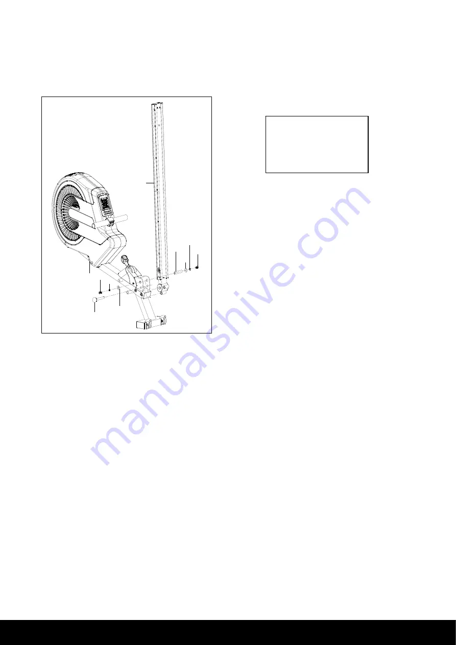
1.  Pull out the ball pin (35) from the main frame (1). 


2.  Insert the slide rail (45) onto the U type connect   


tube of main frame (1), fasten with one axle for slide rail (41),   


two sets of allen bolts (34), spring washers (37) and flat washers (38). 


3.  Then insert the ball pin (35). 


Hardware Step 2 

2 Allen Bolts (#34) 

2 Spring Washers (#37) 

2 Flat Washers (#38) 

1 Axle (#41) 

7

Summary of Contents for YRK56040A

Page 1: ...www yorkfitness com au Owner s Manual TURBINE ROWER Item YRK56040A ...

Page 2: ...ls Please take the time to read this owner s manual as it will help you to get the most out of your new exercise equipment For more information visit www yorkfitness com au Please keep your purchase receipt with this manual ATTENTION THIS ROWER IS INTENDED FOR RESIDENTIAL USE ONLY AND IS WARRANTED FOR THE APPLICATION ANY OTHER APPLICATION VOIDS THIS WARRANTY IN ITS ENTIRETY CONTENTS Pack List 04 A...

Page 3: ...ection of features designed to make your workouts at home more effective and enjoyable For your benefit read this manual carefully before you use the York Fitness Turbine Rower To help us assist you note the product model number and serial number before contacting us Before reading further please familiarize yourself with the parts that are labeled in the drawing below Mid Stabilizer Transport Whe...

Page 4: ...RT NO DESCRIPTION Q TY 1 91 Main frame middle stabilizer 1 9 Front support tube 1 54 Rear support tube 1 53 Seat 1 45 Slide rail 1 14L R Pedal L R 1 1 11L R Fixed bracket for handlebar L R 1 1 3 Roller 2 55 Foot mat 2 13 Allen bolt for pedal 4 35 Ball pin 1 8L R End cap for front stabilizer tube L R 1 1 User manual 1 Hardware pack 1 4 ...

Page 5: ...ing washer 2 38 Flat washer 2 40L End cap for side rail L 1 40R End cap for side rail R 1 41 Axle for slide rail 1 42 Allen bolt 2 43 Flat washer 7 92 Allen key 6MM 2 93 Wrench 13MM 1 Note Above parts are all the parts needed to assemble this machine Before you start to assemble please check the hardware packing to make sure they are included 5 ...

Page 6: ...au Rower Assembly Instructions 1 Middle Stabilizer Rollers 1 2 3 4 2 3 4 1 Attach the rollers 3 onto middle stabilizer fasten with two sets of allen bolt 4 and nylon nut 2 which are pre assembled on the middle stabilizer 6 ...

Page 7: ...rom the main frame 1 2 Insert the slide rail 45 onto the U type connect tube of main frame 1 fasten with one axle for slide rail 41 two sets of allen bolts 34 spring washers 37 and flat washers 38 3 Then insert the ball pin 35 Hardware Step 2 2 Allen Bolts 34 2 Spring Washers 37 2 Flat Washers 38 1 Axle 41 7 ...

Page 8: ...htly fasten with two allen bolts 34 3 Fasten two foot mats 55 on the rear support tube 54 4 Attach the rear support tube 54 to the slide rail 45 fasten with one allen bolt 19 three flat washers 43 and two allen bolts 42 5 Then insert two end caps for side rail 40L R to the end of slide rail 45 Hardware Step 3 2 Cushioned Rubbers 36 2 Allen Bolts 34 1 Allen Bolt 19 3 Flat Washers 43 2 Allen Bolts 4...

Page 9: ... the floor 2 Take off four self tapping screws 10 from the end caps for front stabilizer tube 8L R which are pre assembled on the end caps then attach the end caps to the front support tube 9 by four self tapping screws 10 3 Attach the front support tube 9 to the main frame 1 fasten with four allen bolts 19 Hardware Step 4 4 Allen Bolts 19 9 ...

Page 10: ... on the floor 2 Pull out the ball pin 35 from the main frame and unfold the slide rail 45 Then insert the ball pin 35 to the main frame again to lock in position Note Before inserting the ball pin 35 1 Slightly lift up the main frame 2 Make sure the ball pin holes are lined up 3 Insert ball pin 35 into holes 10 ...

Page 11: ...6mm 1 Insert two fixed brackets for handlebar 11L R into the holes on the front support tube of main frame 1 2 Attach the left pedal 14L to the left side of main frame 1 fasten with two allen bolts 13 3 Repeat for the right pedal 14R to the right side of main frame 1 11 ...

Page 12: ...r 29 1 The handlebar 29 also can be placed into the Handlebar holder 8Folding the Rower 35 1 To fold the machine for storage the ball pin can be removed and the slide rail can be lifted up Remember to replace the pin after folding the slide rail 12 ...

Page 13: ...osen the 3 screws on the right side fo the console Gently ease the console panel out of the shroud 2 On the back panel replace batteries Make sure they fit tightly in the correct postions 3 Place console back into shroud and retighten the 3 screws 13 ...

Page 14: ...Good F3 0 Fair F4 0 below average F5 0 No Good F6 0 Poor RESET Press and hold this button for 2 seconds to reset all of the value to Zero UP Increase the setting value of the following functions TIME COUNT DISTANCE CALORIES and PULSE DOWN Decrease the setting value of the following functions TIME COUNT DISTANCE CALORIES and PULSE Functions TIME Accumulates total work out time from 00 00 up to 99 5...

Page 15: ...onsole will show P You can set a target heart rate before training by pressing UP and DOWN buttons within the rate zone 90 to 220 Each increment is 1 heart beat If you go above your target heart rate the LCD Pulse value will flash and ask you to reduce the intensity of your exercise STROKES PER MINUTE Displays the average stroke count per minute TRAVEL DISTANCE Displays your stroke travel distance...

Page 16: ...d properly at the upright and computer No speed or distance displays on the monitor Sensor wire not connected Ensure the computer wires are connected properly at the upright and the computer Sensor wire not working properly Replace sensor wire Monitor not working properly Replace monitor No tension Air Damper needs Adjustment Adjust tension lever accordingly Squealing Belt slipping Adjust belt 16 ...

Page 17: ...or handlebar L 1 40R End cap for side rail R 2 12 U type bracket for pedal 2 40L End cap for side rail L 2 13 Allen bolt for pedal M12 140 4 41 Axle for slide rail 1 14 R Pedal R 1 42 Allen bolt M8 40 2 14 L Pedal L 1 43 Flat washer ф8 ф17 15 15 Fixed bracket for pedal 2 44 Square end cap 60 30 1 16 Cross head screw M5 12 18 45 Slide rail 1 17 Nylon nut M5 16 46L Slide rail L 1 18 Fixed plate for ...

Page 18: ...ZZ 2 82 Belt 1 63 Pulley 1 83 Self tapping screw ST5 30 8 64 Tension rope 1 84 Powder metal 2 65 Guy cable 1 85 Pulley 1 66 Bearing bracket 2 86 Axle for pulley 1 67 Clamp spring Ф17 4 87 Air outlet 1 68 Bearing 6003ZZ 2 88 Self tapping screw 6 69 Bearing bracket 2 89R Chain cover R 1 70 Fixed plate for bearing 2 89L Chain cover L 1 71 Axle for wind turbine 1 90 Woven tape 1 72 Bushing 6 91 Middle...

Page 19: ... 1 7 1 8 1 8 1 8 1 8 1 9 1 9 2 0 L 1 6 1 6 1 0 2 1 2 1 2 2 2 2 2 8 2 9 3 0 3 1 3 2 3 3 2 0 R 3 4 3 4 3 4 3 4 3 4 3 5 3 6 3 6 3 4 3 6 3 6 3 7 3 8 3 9 4 0 L 4 0 R 4 1 4 0 R 4 0 L 3 9 3 8 3 7 4 2 4 3 4 3 4 3 4 4 4 5 4 6 L 4 6 R 4 7 4 7 4 7 4 7 4 7 4 7 4 7 4 7 4 7 2 4 8 4 9 5 0 5 1 5 2 5 3 5 4 5 5 5 5 5 6 5 6 1 2 3 4 2 3 4 5 5 1 9 1 9 5 4 3 4 3 9 1 9 2 19 ...

Page 20: ... 3 4 3 8 9 L 8 9 R 5 7 L 5 7 R 8 8 8 8 8 8 8 8 8 8 8 7 5 8 5 9 6 0 6 1 6 2 6 2 6 3 2 2 3 1 3 1 3 1 6 6 6 6 6 7 6 8 6 9 6 7 7 0 7 1 6 7 7 0 6 9 6 8 6 7 7 2 7 2 7 2 7 3 7 4 7 5 7 5 7 6 7 7 7 8 7 9 8 0 8 1 8 2 8 3 8 3 8 3 8 3 8 3 8 3 8 3 8 4 8 0 8 5 8 0 8 6 8 4 9 0 2 7 8 3 2 6 2 5 2 4 2 3 20 ...

Page 21: ...010 For efficient processing of your enquiry please have relevant date of purchase retailer name you purchased the item from and the brand on the product This warranty does not extend to any damage to a product caused by abuse improper or abnormal usage as detailed in this instruction manual or repairs not provided by BOYLES Nor does this warranty extend to products used for commercial or rental p...

Page 22: ... email our service department at spares boylesfitness com au including your best contact details proof of purchase serial number and a brief explanation of what is wrong Emailing is the quickest and most reliable way to get your service request processed Once we have your details we will either call or email you back with the next steps The quickest way once we determine the problem and send you a...

Page 23: ... in an application or the incorrect environment that is not recommended by BFE or as not stipulated in the owner s manual such as a commercial rental environment will void the warranty set forth by BFE j BFE recommends the use of a protective rubber floor mat This reduces the incidence of dust and lint collection around the motor reduces noise protects your floor You can purchase this from your re...

Page 24: ...rranty period Metropolitan Area defined as no more that 50km from G P O in all capital cities Disclaimer Our goods come with guarantees that cannot be excluded under the Australian Consumer Law You are entitled to a replacement or refund for a Major failure and for compensation for any other Reasonable foreseeable loss or damage You are also entitled to have goods repaired or replaced if the goods...

Reviews: