107273-UUM-C-0306
4
Unitary Products Group
To Turn Off the Appliance:
1.
Set the thermostat to lowest setting.
2.
Turn off all electric power to the appliance if service is to be per-
formed.
3.
Remove burner access panel.
4.
Turn the valve attached to the oil pump to the closed position.
5.
Replace burner access panel.
NOTE: When opening valve attached to the oil pump. turn handle until
valve opens to a snug stop. DO NOT torque down handle as this will
strip threads and valve will need to be replaced.
FURNACE USER MAINTENANCE
Air Filters
Dirty filters greatly restrict the flow of air and may cause damage to the
moving parts of the furnace. If the filters become clogged the heat
exchangers and blower motor could overheat resulting in a potentially
dangerous situation.
The filters should be checked every 3 months. On new construction,
check the filters every week for the first four weeks and every three
weeks after that, especially if the indoor fan is running continuously.
When replacing the filter(s) you must use filters that are the same size
as those recommended in Table 1. Never operate your furnace without
a suitable air filter. NEVER use PLEATED MEDIA or HOGS HAIR air fil-
ters in this furnace.
Every time the filters are changed the following items should be visually
inspected:
•
Check vent pipe for blockage or leakage.
•
Check all components to be sure they are in good condition and
that there are no obvious signs of deterioration.
•
Check for dirt or lint on any surfaces or on components. Do not try
to clean any of the surfaces or components. Cleaning of the fur-
nace and its components must be done by a qualified service pro-
fessional.
Removing Filters
Internally Mounted Air Filters
The air filter is in a rack that is attached to the inside of the louvered
blower door. Refer to Figure 7 for air filter location.
To remove the filter you must do the following:
1.
Before proceeding, be sure the area is well ventilated. Follow
instruction “To turn off the appliance”. Check all metal parts and
surfaces to be sure they have cooled to room temperature before
you begin.
2.
Remove the louvered blower door by pulling on the indentated
handles on both sides of the bottom of the door.
3.
Remove the air filter by sliding them down. The air filter will slide
out of the rack.
4.
Replace throw away filter(s) with the same size new filter(s) and
the same type air filter(s). DO NOT use pleated media, hogs hair,
or cleanable air filters.
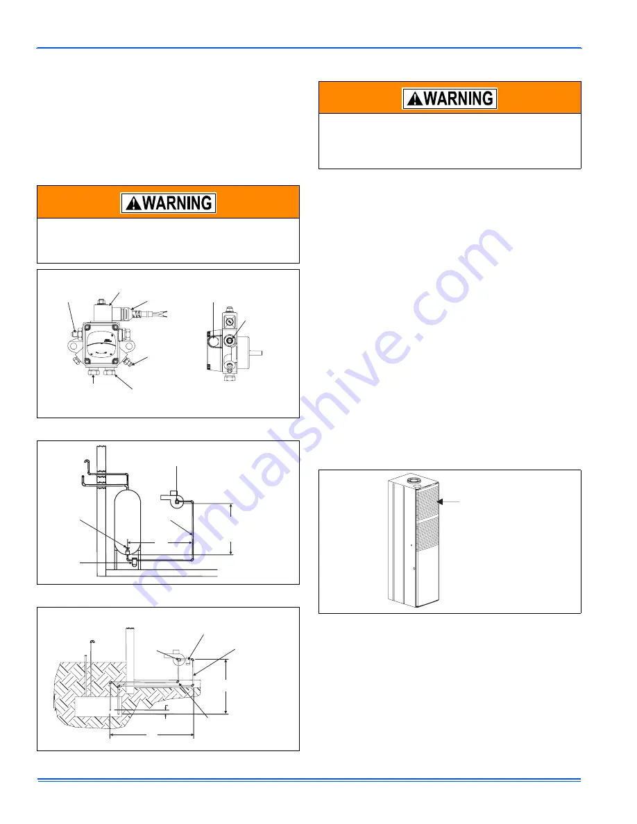
Should overheating occur, or the oil burner fail to shut off, turn
the external manual valve on the oil pump or oil line at the oil
tank to the off position and let the furnace cool off before shut-
ting off the electrical power supply. Refer to Figures 4, 5, and 6.
FIGURE 4: Oil Pump
FIGURE 5: One-Pipe System
FIGURE 6: Two-Pipe System
4 GPH 100-150 PSI 3450 RPM
3 GPH 150-200 PSI 3450 RPM
NO. 2 & LIGHTER FUEL
INLET
BY-PASS
Exclusively for Beckett
Made by Suntec
INLET
NO. 2 FUEL
A2EA-6520
Beckett
CLEAN
CUT
USE ONLY WITH
VALVE ON DELAY
Pressure
Adjustment
Screw
Inlet Port
1/4 NPTF
Bleed &
Gauge Port
Return Port
Install 1/16” by Pass Pipe
Plug For Two-Pipe System Only
(Use 5/32” Allen Wrench)
Cordset
By Pass
Solenoid
Valve
Inlet Port
1/4 NPTF
(0.64 cm)
Nozzle Port
3/16 Flare
Fittting
Oil
Tank
Maximum
One Pipe (H)
Lift: 8 Ft
“R”
Inlet
Fuel Unit
Primary
Filter
Shut-Off
Valve
Fill
Pipe
Air
Vent
L = H + R
Oil
Tank
Fill
Pipe
Air
Vent
Outside Tank Fuel Unit
Above Bottom of Tank
Fuel
Unit
Inlet
Primary
Filter
L = H + R
“R”
“H”
Use Protective Plastic
Tubing in Concrete or as
Local Codes Require
3” - 4”
Before proceeding, be sure the area is well ventilated. Turn the
thermostat OFF. If the blower is running, wait until it stops auto-
matically. Turn OFF the oil and electrical power supplies to the
furnace. Check all metal parts and surfaces to be sure they
have cooled to room temperature before you begin.
FIGURE 7: Furnace Air Filters
Air Filters Can Be
Found On The Inside
Of This Access Panel


