


2.
Remove the rooftop return air access panels. Remove
and discard any hoods, power exhaust equipment, or
economizer.
See Figure 1.
PAGE 2
BALANCING DAMPER
MAXA-MI$ER
Ô
UNITARY ENERGY RECOVERY VENTILATOR
MODEL VR011A12H & B12H (STATIONARY)
INSTALLATION
INSTRUCTIONS
5257541-UAI-A-0616 / R11A-29YSDW
Figure 3
QUADRANT
Figure 4
Figure 1
RETURN AIR ACCESS PANEL
Figure 2
3.
Locate the provided field wiring harness and the RTUs
accessory wiring bundle, separate the "com" and
"ex-fan" control wires from the accessory wiring
bundle (look for small white plugs).
See Figure 2.
Figure 5
8.
Connect the communication wire and power wire
located in the accessory wiring bundle in the RTU
return air section to the proper terminals on the
economizer control board (see SE field harness
diagram at the back of this manual)
9.
Route the field wiring harness into the return air
section of the rooftop unit, coil the excess wire inside
the RTU in order to keep it clear during the installation
of the UERV.
10. Locate provided rolls of ¾" and
1
8
" gasket material.
Apply ¾" gasket to the middle and bottom decks or the
UERV, apply the
1
8
" gasket to the perimeter of the
transition assembly that connects the RTU to the
UERV.
4.
Install the provided balancing damper assembly into
the return air section of the RTU.
See Figure 3.
5.
Adjusting the balancing damper for the minimum
airflow requirements can be done by loosening the
wingnut on the quadrant and then moving the
quadrant handle to set the return dampers in place.
See Figure 4.
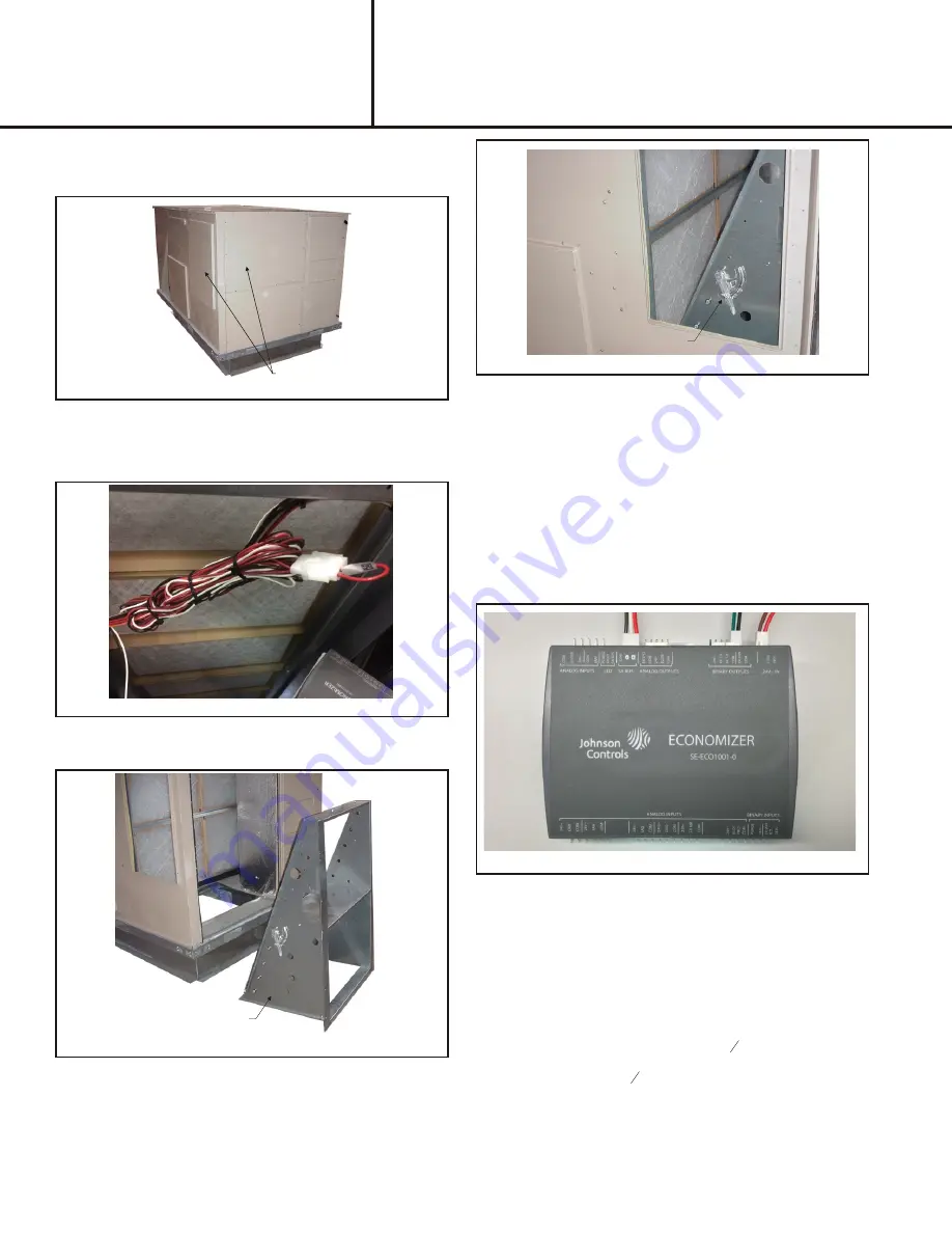
6.
Install SE ECO 1001 economizer control board on
balancing damper. From the RTUs accessory wiring
bundle plug the 3 wire (Red, Black, White)
Communications plug into the "SA Bus" port of the
economizer control board, plug the 2 wire exhaust fan
plug (Red, Brown) into the "24V- IN" terminal. From the
field wiring harness plug the 2 wire ERV Occupied plug
(Green, Black) into the "ex fan/ com" plug in the binary
outputs section of the board.
See wiring diagram
7.
Mount the SE-8001001 economizer control board in
the return air compartment on the balancing damper
frame within reach of field wiring harness.
See Figure
5.


