background image

PAGE 3

MAXA-MI$ER

Ô

UNITARY ENERGY RECOVERY VENTILATOR

MODEL VR011A12H & B12H (STATIONARY) 

 INSTALLATION

INSTRUCTIONS

5257541-UAI-A-0616 / R11A-29YSDW
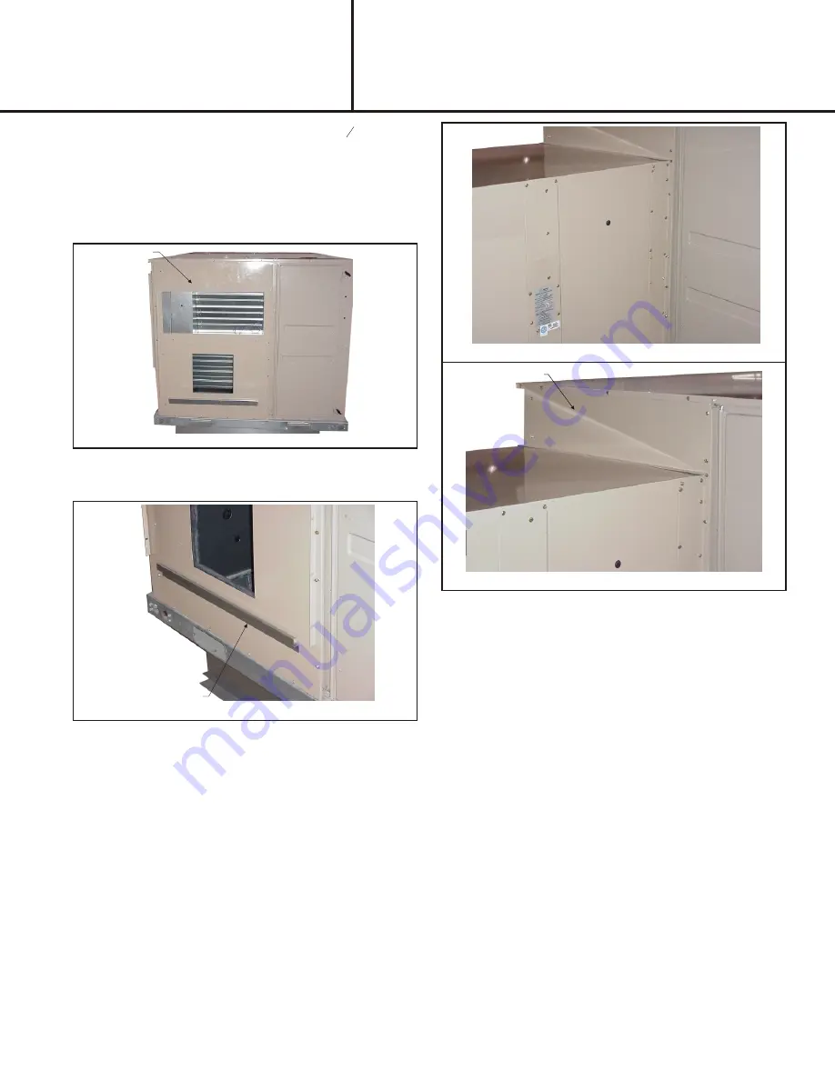
Figure 8

Figure 9

TOP FILLER PANEL

Figure 7

PLATFORM SUPPORT RAIL

ADAPTOR

Figure 6

11. Locate the provided adaptor panel. Apply 

1

8

" gasket to

the perimeter of the  panel to seal the contact between
the  UERV and the RTU. Install the adaptor panel on
the RTU replacing the return air access panels
removed earlier and secure with provided screws,
screw holes will line up. (VR011A12H may also
require a filler panel installed after the UERV). 

See

Figure 6.

12. Secure the platform support rail to the bottom of the

adaptor panel using the provided screws. 

See Figure

7.

13. Lift the UERV at least 3' (feet), remove the 4 screws

holding each leg to its guide and pull out the legs.
Reinsert each leg from the bottom with the flat foot
under the unit then reinsert one of the screws to hold it
in place. Do not insert other screws at this time as the
legs will have to be adjusted once the unit is finally set
in place.

14. Position the UERV in front of the return air section of

the rooftop unit, line up the UERV with the adaptor
panel. 

See Figure 8.

15. Lower the UERV on to the platform support rail, then

secure the UERV to the adaptor panel using the
provided screws.

16. On units requiring a top filler panel install panel by

tucking the top of the panel under the top of the RTU
and angling in so that the bottom of the panel covers
the top flange of the UERV. Secure with provided
screws. 

See Figure 9.

Note: An equipment support or pressure treated

2x6x48" piece of wood should be placed under the
end of the UERV to prevent roof penetration by the
standoff legs.

17. Remove the screw placed in the standoff legs in 

Step

13


and adjust the legs on the UERV so that it is level.

Insert all 4 screws into each leg so that the legs are
secure and the UERV sits in a leveled position.

18. Check along the edges where the UERV meets the

adaptor panels and where the adapter panels meet
the RTU and seal where necessary. There should be
no air leakage and the final UERV assembly should be
weather tight. Final assembly should resemble 

Figure 

10

.

19. On the UERV open the access panel on the right side

of the name plate.

20. Connect the wiring harness to the 3 prong connector

located near the bottom of this access panel on one
end and the "ex-fan" and "com" connectors on the
other.

21. Once high voltage connections are complete and unit

is ready to start, power RTU and UERV and program
SE controller to run the UERV.  

Summary of Contents for VR011A12H

Page 1: ...37 Lbs Crated 2 Remove crating and retrieve bag assembly that is inside of UERV 3 All panels must be in place for rigging 4 Lifting straps are needed to lift the unit CAUTION Danger of sharp metallic edges Can cause injury Take care when servicing unit to avoid accidental contact with sharp edges WARNING Electric shock hazard Can cause injury or death Before attempting to perform any service or ma...

Page 2: ...he installation of the UERV 10 Locate provided rolls of and 1 8 gasket material Apply gasket to the middle and bottom decks or the UERV apply the 1 8 gasket to the perimeter of the transition assembly that connects the RTU to the UERV 4 Install the provided balancing damper assembly into the return air section of the RTU See Figure 3 5 Adjusting the balancing damper for the minimum airflow require...

Page 3: ...ee Figure 8 15 Lower the UERV on to the platform support rail then secure the UERV to the adaptor panel using the provided screws 16 On units requiring a top filler panel install panel by tucking the top of the panel under the top of the RTU and angling in so that the bottom of the panel covers the top flange of the UERV Secure with provided screws See Figure 9 Note An equipment support or pressur...

Page 4: ... media is polymeric material that is coated and permanently bonded with a dry desiccant for total enthalpy recovery The wheel is belt driven by PSC motor and drive belt When slowly rotating through counter flowing exhaust and fresh air streams the UERV adsorbs sensible heat and latent heat from the warmer air stream and transfer this total energy to the cooler air stream during the second half of ...

Page 5: ...r dampers installed inside the RTUs return air section Adjustment of the damper is made by loosening the wingnut adjusting the damper blades and then tightening the wingnut before closing the panel and measuring again 4 Once desired the CFM is reached replace the plastic plugs in the access holes in the doors X Maintenance Motor Maintenance All motors use prelubricated sealed bearings no further l...

Page 6: ...Options AA No Options Installed L1 Low Ambient Kit LAK L2 LAK MOA L3 LAK MOA SSJ not used on P models L4 LAK MOA SSJ PS not used on P models L5 LAK SSJ not used on P models L6 LAK SSJ PS not used on P models L7 LAK PS L8 LAK MOA and PS M1 Motorized Outside Air MOA M2 MOA SSJ not used on P models M3 MOA SSJ PS PS not used on P models M4 MOA PS S1 Stop Start Job SSJ not used on P models S2 SSJ PS no...

Page 7: ...PAGE 7 ...

Page 8: ...PAGE 8 ...

Page 9: ...ack Field Harness J160 Jack Damper Motor Harness J161 Jack Damper Exhaust Motor Harness K163 Relay Exhaust Air Motor K164 Relay Fresh Air Motor MPD 1 Missing Pulse Detector Board Optional P48 Plug Fresh Air Motor Harness P50 Plug Wheel Motor Harness P51 Plug Exhaust Air Motor Harness P56 Plug Damper Motor Harness P148 Plug Fresh Air Motor P150 Plug Wheel Motor P151 Plug Exhaust Air Motor P152 Plug...

Page 10: ... p O 5 r e p m a d e k a t n i d e z i r o t o m l a n o i t p O 6 l o r t n o c g o j d n a t r a t s p o t s l a n o i t p O 7 d e e p s O L r o D E M r o f e r i w e r o t p u t e s d e e p s I H e h t s w o h s m a r g a i D s d e e p s O L r o D E M I H r o f d e r i w e b y a m t i n U 1 0 1 K B o t 1 0 1 H W t c e n n o c o s l A O L r o f 1 0 1 D R r o D E M r o f 1 0 1 L B t c e n n o c d...

Page 11: ...EQUIPMENT LAYOUT PAGE 11 ...

Page 12: ... ERV II SE Procedures to Backup Restore 1 Once the packaged unit is powered up the 120 second startup delay begins Once the delay expires there may or may not be a Start Up delay displayed To cancel the second time delay press the Cancel button for six seconds See Figure 1 Startup Figure 1 Update Figure 2 Backup Figure 3 2 Once the control is out of time delay mode press the Joystick down through ...

Page 13: ...ast you return by pressing the joy stick lever up until the Update screen appears Screen will read Contrler Controller Update Enter Cancel Buttons Figure 6 View Ver Figure 7 LoadFirm Figure 8 Confirm Figure 9 USB OK Figure 4 4 Press ENTER Screen will read View Ver Version Load Firm Backup 5 Toggle Joy stick down so the arrow is next to Load Firm 6 Press ENTER Screen shows software versions present...

Page 14: ...it control 1 Scroll through menus by pressing down on joystick Status Alarms Summary Commission Econ Economizer Enable Make sure this is set to Yes ERV En Figure 11 Econ En Figure 10 3 The economizer minimum setting must be set at 50 or greater Status Alarms Summary Commission PowerEx ERV Enable Make sure this is set to Yes 4 Once the ERV is set to Enable the ERV will operate any time the unit is ...

Page 15: ...PAGE 15 MAXA MI ERÔ UNITARY ENERGY RECOVERY VENTILATOR MODEL VR011A12H B12H STATIONARY INSTALLATION INSTRUCTIONS 5257541 UAI A 0616 R11A 29YSDW This Page Intentionally Left Blank ...

Page 16: ...apter panels as required Follow accessory and unit installation manuals q Verify field wiring including the wiring to any accessories q Check all multi tap transformers to insure they are set to the proper incoming voltage q Verify correct belt tension as well as the belt pulley alignment Tighten if needed q Prior to energizing the unit inspect all the electrical connections q Power the unit Bump ...

Reviews: