background image

PAGE 4

MAXA-MI$ER

Ô

UNITARY ENERGY RECOVERY VENTILATOR

MODEL VR011A12H & B12H (STATIONARY) 

 INSTALLATION

INSTRUCTIONS

5257541-UAI-A-0616 / R11A-29YSDW

Figure 11

DELTA PRESSURE

(FRESH AIR)

DELTA PRESSURE

(EXHAUST AIR)

OPTIONAL EQUIPMENT SUPPORT

Figure 10

22. All electrical connections must meet current National

Electric Codes (NEC) and/or Canadian Electric Code
(CEC). Refer closely to the wiring diagram in unit or in
these instructions for proper connections. Refer to the
units Nameplate for the minimum circuit ampacity and
the Maximum Over Current protection size. Electrical
data is listed both on the nameplates and the individual 
motor nameplates.

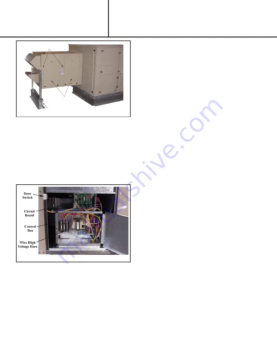
23. Connect the line voltage power to the UERV from a

field installed power disconnect through provided ¾"
knockout. Connect line voltage to the fused power
block per wiring diagram, 

Figure 11

 shows the control

box and wiring.

24. Ground the unit with a suitable ground connection

either through the supply wiring or and earth ground.

Units voltage entries must be sealed weather tight
after wiring is complete.

25. Restore power to the unit.

26. Start system up to verify operation.

27. Replace access panels on UERV and return air

section of the RTU and secure.

28. Cleanup once UERV is operating properly, caulk open

joints holes or seams to make the unit weather tight.

29. Fill out installation checklist and startup sheet in the

back of these instructions.

30. Leave this manual with the owner or in an envelope

inside the unit.

VIII  -  Op er a tion

How It Works

The unit contains an Energy Recovery Wheel (ERW) that
is a new concept in rotary air-to-air heat exchanger.
Designed as a packaged unit for ease of installation and
maintenance, only matching up to rooftop unit with an
internal balancing damper and connection of electrical
power is required to make the system operational. The
concept consists of a unique rotary energy recovery wheel
that rotates in and out of fresh air streams within a heavy
duty, permanently installed blower cabinet that provides
ready access to all internal components. The media is
polymeric material that is coated and permanently bonded
with a dry desiccant for total enthalpy recovery. The wheel
is belt driven by PSC motor and drive belt.

When slowly rotating through counter flowing exhaust and
fresh air streams the UERV adsorbs sensible heat and
latent heat from the warmer air stream and transfer this
total energy to the cooler air stream during the second half
of its rotating cycle. Rotating at 60 revolutions per minute,
the wheel provides constant flow of energy  from warmer to 
cooler air stream. The large energy transfer surface and
laminar flow through the wheel causes  this constant flow
of recovered energy to represent up to 85% of the
difference in total energy contained within the two air
streams.

Sensible and latent heat are the two components of total
heat. Sensible heat is energy contained in dry air and latent 
heat is the energy contained within the moisture of the air.
The latent heat load from the outdoor fresh air on an air
conditioning system can often be two to three times that of
the sensible heat load and in the winter it is a significant
part of a humidification heat load.

During both the summer and winter, the UERV transfers
moisture entirely in the vapor phase. This eliminates wet
surfaces that retain dust and promote fungal growth as well 
as the need for a condensate pan and drain to carry water.

Because it is constantly rotating when in the air stream, the
UERV is always being cleared by air, first in one direction
then the other. Because it is always dry, dust or other
particles impinging on the surface during one half cycle,
are readily removed during the next half cycle.

Additional Information for Options are provided in
Options Manual

.

Re cov ery  Mode

On a thermostat call for blower operation in heating,
cooling or continuous blower, the ERW will rotate between
fresh air and exhaust air streams. Both the fresh air and
exhaust air blowers will also be operating to overcome the
air resistance of the UERV.

Free Cool ing Mode (op tional)

The Start, Stop, Jog kit is an optional control board with
temperature and/or enthalpy sensor(s) that stops the
enthalpy wheel from spinning (and transferring heat) when
temperature  conditions are conducive for free cooling.

Summary of Contents for VR011A12H

Page 1: ...37 Lbs Crated 2 Remove crating and retrieve bag assembly that is inside of UERV 3 All panels must be in place for rigging 4 Lifting straps are needed to lift the unit CAUTION Danger of sharp metallic edges Can cause injury Take care when servicing unit to avoid accidental contact with sharp edges WARNING Electric shock hazard Can cause injury or death Before attempting to perform any service or ma...

Page 2: ...he installation of the UERV 10 Locate provided rolls of and 1 8 gasket material Apply gasket to the middle and bottom decks or the UERV apply the 1 8 gasket to the perimeter of the transition assembly that connects the RTU to the UERV 4 Install the provided balancing damper assembly into the return air section of the RTU See Figure 3 5 Adjusting the balancing damper for the minimum airflow require...

Page 3: ...ee Figure 8 15 Lower the UERV on to the platform support rail then secure the UERV to the adaptor panel using the provided screws 16 On units requiring a top filler panel install panel by tucking the top of the panel under the top of the RTU and angling in so that the bottom of the panel covers the top flange of the UERV Secure with provided screws See Figure 9 Note An equipment support or pressur...

Page 4: ... media is polymeric material that is coated and permanently bonded with a dry desiccant for total enthalpy recovery The wheel is belt driven by PSC motor and drive belt When slowly rotating through counter flowing exhaust and fresh air streams the UERV adsorbs sensible heat and latent heat from the warmer air stream and transfer this total energy to the cooler air stream during the second half of ...

Page 5: ...r dampers installed inside the RTUs return air section Adjustment of the damper is made by loosening the wingnut adjusting the damper blades and then tightening the wingnut before closing the panel and measuring again 4 Once desired the CFM is reached replace the plastic plugs in the access holes in the doors X Maintenance Motor Maintenance All motors use prelubricated sealed bearings no further l...

Page 6: ...Options AA No Options Installed L1 Low Ambient Kit LAK L2 LAK MOA L3 LAK MOA SSJ not used on P models L4 LAK MOA SSJ PS not used on P models L5 LAK SSJ not used on P models L6 LAK SSJ PS not used on P models L7 LAK PS L8 LAK MOA and PS M1 Motorized Outside Air MOA M2 MOA SSJ not used on P models M3 MOA SSJ PS PS not used on P models M4 MOA PS S1 Stop Start Job SSJ not used on P models S2 SSJ PS no...

Page 7: ...PAGE 7 ...

Page 8: ...PAGE 8 ...

Page 9: ...ack Field Harness J160 Jack Damper Motor Harness J161 Jack Damper Exhaust Motor Harness K163 Relay Exhaust Air Motor K164 Relay Fresh Air Motor MPD 1 Missing Pulse Detector Board Optional P48 Plug Fresh Air Motor Harness P50 Plug Wheel Motor Harness P51 Plug Exhaust Air Motor Harness P56 Plug Damper Motor Harness P148 Plug Fresh Air Motor P150 Plug Wheel Motor P151 Plug Exhaust Air Motor P152 Plug...

Page 10: ... p O 5 r e p m a d e k a t n i d e z i r o t o m l a n o i t p O 6 l o r t n o c g o j d n a t r a t s p o t s l a n o i t p O 7 d e e p s O L r o D E M r o f e r i w e r o t p u t e s d e e p s I H e h t s w o h s m a r g a i D s d e e p s O L r o D E M I H r o f d e r i w e b y a m t i n U 1 0 1 K B o t 1 0 1 H W t c e n n o c o s l A O L r o f 1 0 1 D R r o D E M r o f 1 0 1 L B t c e n n o c d...

Page 11: ...EQUIPMENT LAYOUT PAGE 11 ...

Page 12: ... ERV II SE Procedures to Backup Restore 1 Once the packaged unit is powered up the 120 second startup delay begins Once the delay expires there may or may not be a Start Up delay displayed To cancel the second time delay press the Cancel button for six seconds See Figure 1 Startup Figure 1 Update Figure 2 Backup Figure 3 2 Once the control is out of time delay mode press the Joystick down through ...

Page 13: ...ast you return by pressing the joy stick lever up until the Update screen appears Screen will read Contrler Controller Update Enter Cancel Buttons Figure 6 View Ver Figure 7 LoadFirm Figure 8 Confirm Figure 9 USB OK Figure 4 4 Press ENTER Screen will read View Ver Version Load Firm Backup 5 Toggle Joy stick down so the arrow is next to Load Firm 6 Press ENTER Screen shows software versions present...

Page 14: ...it control 1 Scroll through menus by pressing down on joystick Status Alarms Summary Commission Econ Economizer Enable Make sure this is set to Yes ERV En Figure 11 Econ En Figure 10 3 The economizer minimum setting must be set at 50 or greater Status Alarms Summary Commission PowerEx ERV Enable Make sure this is set to Yes 4 Once the ERV is set to Enable the ERV will operate any time the unit is ...

Page 15: ...PAGE 15 MAXA MI ERÔ UNITARY ENERGY RECOVERY VENTILATOR MODEL VR011A12H B12H STATIONARY INSTALLATION INSTRUCTIONS 5257541 UAI A 0616 R11A 29YSDW This Page Intentionally Left Blank ...

Page 16: ...apter panels as required Follow accessory and unit installation manuals q Verify field wiring including the wiring to any accessories q Check all multi tap transformers to insure they are set to the proper incoming voltage q Verify correct belt tension as well as the belt pulley alignment Tighten if needed q Prior to energizing the unit inspect all the electrical connections q Power the unit Bump ...

Reviews: