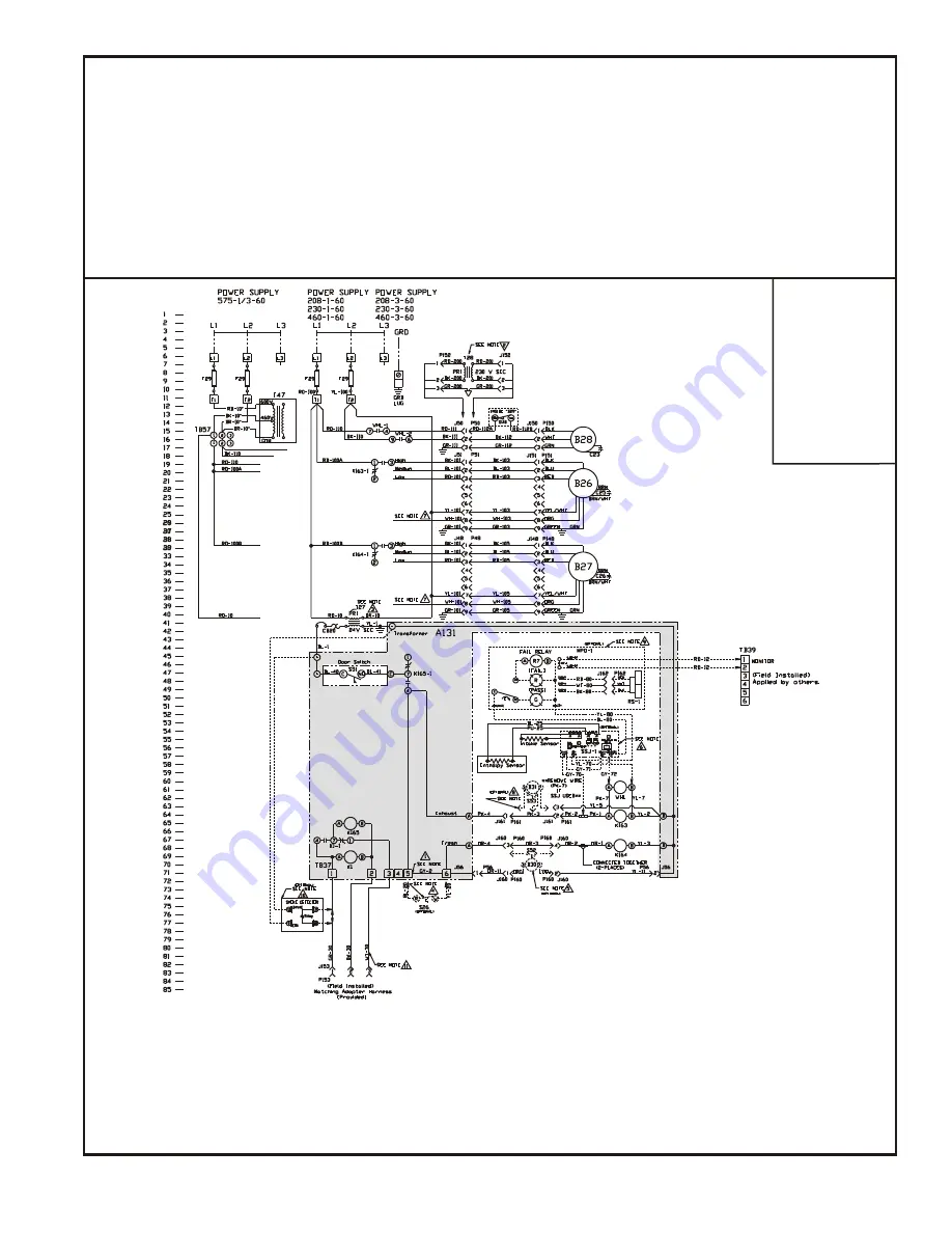
background image

PAGE 9

R11A-29YSDW

COMPONENT CODE

A131

Fixed Relay Board

B26

Motor, Exhaust Air

B27

Motor, Fresh Air

B28

Motor, Desiccant Wheel

B30

Motor, Damper (Optional)

B31

Motor, Damper Exhaust (Optional)

C23

Capacitor, Wheel Motor

C25

Capacitor, Motor Exhaust Air

C26

Capacitor, Motor Fresh Air

F29

Fuse

J48

Jack, Control Box (Fresh Air)

J50

Jack, Control Box (Wheel)

J51

Jack, Control Box (Exhaust Air)

J56

Jack, Control Box (Damper)

J148

Jack, Fresh Air Motor Harness

J150

Jack, Wheel Motor Harness

P153

Plug, Field Harness

P160

Plug, Damper Motor

P161

Plug, Damper Exhaust Motor Harness

RS-1

Rotation Sensor (Optional)

S26

Switch, Low Ambient (Optional)

S51

Switch, Door

S52

Switch, Damper Intake

S53

Switch, Damper Exhaust

SSJ

Climate Smart Board (Optional)

T27

Transformer, Control

T28

Transformer, Step-down (Optional)

T47

Transformer, Step-down (Optional)

TB37

Terminal Block (Low Voltage)

TB38

Terminal Block (Monitoring)

TB57

Terminal Block (High Voltage)

WHL

Relay, Wheel Motor

J151

Jack, Exhaust Air Motor Harness

J152

Jack, Transformer (High Voltage)

J153

Jack, Field Harness

J160

Jack, Damper Motor Harness

J161

Jack, Damper Exhaust Motor Harness

K163

Relay, Exhaust Air Motor

K164

Relay, Fresh Air Motor

MPD-1

Missing Pulse Detector Board (Optional)

P48

Plug, Fresh Air Motor Harness

P50

Plug, Wheel Motor Harness

P51

Plug, Exhaust Air Motor Harness

P56

Plug, Damper Motor Harness

P148

Plug, Fresh Air Motor

P150

Plug, Wheel Motor

P151

Plug, Exhaust Air Motor

P152

Plug, Transformer (High Voltage)

WIRE COLOR 

CODE

BK

Black

BL

Blue

GR

Green

GY

Gray

OR

Orange

PK

Pink

RD

Red

WT

White

YL

Yellow

Notes:
1. Re move jumper to in stall field op tional low am bi ent switch.
2. Step-down trans former as sem bly for 460/575 volt units (only) con nect be tween J50 and P50.
3. Se lec tive volt age ter mi nal for proper unit volt age.
4. Op tional  low  am bi ent  switch.
5. Op tional  mo tor ized  in take  damper.
6. Op tional stop, start and jog con trol.
7. Unit may be wired for HI, MED, or LO speeds. Di a gram shows the HI speed setup, to re wire for MED or LO speed,

 dis con nect BK-101 from re lays and con nect BL-101 for MED, or RD-101 for LO. Also con nect WH-101 to BK-101.

8. Op tional  mo tor ized  ex haust  damper.
9. Op tional  wheel  ro ta tion  sen sor.
10. Op tional  smoke  de tec tor
11. Match ing adapter har ness (pro vided) to con nect with roof top unit.

Summary of Contents for VR011A12H

Page 1: ...37 Lbs Crated 2 Remove crating and retrieve bag assembly that is inside of UERV 3 All panels must be in place for rigging 4 Lifting straps are needed to lift the unit CAUTION Danger of sharp metallic edges Can cause injury Take care when servicing unit to avoid accidental contact with sharp edges WARNING Electric shock hazard Can cause injury or death Before attempting to perform any service or ma...

Page 2: ...he installation of the UERV 10 Locate provided rolls of and 1 8 gasket material Apply gasket to the middle and bottom decks or the UERV apply the 1 8 gasket to the perimeter of the transition assembly that connects the RTU to the UERV 4 Install the provided balancing damper assembly into the return air section of the RTU See Figure 3 5 Adjusting the balancing damper for the minimum airflow require...

Page 3: ...ee Figure 8 15 Lower the UERV on to the platform support rail then secure the UERV to the adaptor panel using the provided screws 16 On units requiring a top filler panel install panel by tucking the top of the panel under the top of the RTU and angling in so that the bottom of the panel covers the top flange of the UERV Secure with provided screws See Figure 9 Note An equipment support or pressur...

Page 4: ... media is polymeric material that is coated and permanently bonded with a dry desiccant for total enthalpy recovery The wheel is belt driven by PSC motor and drive belt When slowly rotating through counter flowing exhaust and fresh air streams the UERV adsorbs sensible heat and latent heat from the warmer air stream and transfer this total energy to the cooler air stream during the second half of ...

Page 5: ...r dampers installed inside the RTUs return air section Adjustment of the damper is made by loosening the wingnut adjusting the damper blades and then tightening the wingnut before closing the panel and measuring again 4 Once desired the CFM is reached replace the plastic plugs in the access holes in the doors X Maintenance Motor Maintenance All motors use prelubricated sealed bearings no further l...

Page 6: ...Options AA No Options Installed L1 Low Ambient Kit LAK L2 LAK MOA L3 LAK MOA SSJ not used on P models L4 LAK MOA SSJ PS not used on P models L5 LAK SSJ not used on P models L6 LAK SSJ PS not used on P models L7 LAK PS L8 LAK MOA and PS M1 Motorized Outside Air MOA M2 MOA SSJ not used on P models M3 MOA SSJ PS PS not used on P models M4 MOA PS S1 Stop Start Job SSJ not used on P models S2 SSJ PS no...

Page 7: ...PAGE 7 ...

Page 8: ...PAGE 8 ...

Page 9: ...ack Field Harness J160 Jack Damper Motor Harness J161 Jack Damper Exhaust Motor Harness K163 Relay Exhaust Air Motor K164 Relay Fresh Air Motor MPD 1 Missing Pulse Detector Board Optional P48 Plug Fresh Air Motor Harness P50 Plug Wheel Motor Harness P51 Plug Exhaust Air Motor Harness P56 Plug Damper Motor Harness P148 Plug Fresh Air Motor P150 Plug Wheel Motor P151 Plug Exhaust Air Motor P152 Plug...

Page 10: ... p O 5 r e p m a d e k a t n i d e z i r o t o m l a n o i t p O 6 l o r t n o c g o j d n a t r a t s p o t s l a n o i t p O 7 d e e p s O L r o D E M r o f e r i w e r o t p u t e s d e e p s I H e h t s w o h s m a r g a i D s d e e p s O L r o D E M I H r o f d e r i w e b y a m t i n U 1 0 1 K B o t 1 0 1 H W t c e n n o c o s l A O L r o f 1 0 1 D R r o D E M r o f 1 0 1 L B t c e n n o c d...

Page 11: ...EQUIPMENT LAYOUT PAGE 11 ...

Page 12: ... ERV II SE Procedures to Backup Restore 1 Once the packaged unit is powered up the 120 second startup delay begins Once the delay expires there may or may not be a Start Up delay displayed To cancel the second time delay press the Cancel button for six seconds See Figure 1 Startup Figure 1 Update Figure 2 Backup Figure 3 2 Once the control is out of time delay mode press the Joystick down through ...

Page 13: ...ast you return by pressing the joy stick lever up until the Update screen appears Screen will read Contrler Controller Update Enter Cancel Buttons Figure 6 View Ver Figure 7 LoadFirm Figure 8 Confirm Figure 9 USB OK Figure 4 4 Press ENTER Screen will read View Ver Version Load Firm Backup 5 Toggle Joy stick down so the arrow is next to Load Firm 6 Press ENTER Screen shows software versions present...

Page 14: ...it control 1 Scroll through menus by pressing down on joystick Status Alarms Summary Commission Econ Economizer Enable Make sure this is set to Yes ERV En Figure 11 Econ En Figure 10 3 The economizer minimum setting must be set at 50 or greater Status Alarms Summary Commission PowerEx ERV Enable Make sure this is set to Yes 4 Once the ERV is set to Enable the ERV will operate any time the unit is ...

Page 15: ...PAGE 15 MAXA MI ERÔ UNITARY ENERGY RECOVERY VENTILATOR MODEL VR011A12H B12H STATIONARY INSTALLATION INSTRUCTIONS 5257541 UAI A 0616 R11A 29YSDW This Page Intentionally Left Blank ...

Page 16: ...apter panels as required Follow accessory and unit installation manuals q Verify field wiring including the wiring to any accessories q Check all multi tap transformers to insure they are set to the proper incoming voltage q Verify correct belt tension as well as the belt pulley alignment Tighten if needed q Prior to energizing the unit inspect all the electrical connections q Power the unit Bump ...

Reviews: