


PAGE 13
MAXA-MI$ER
Ô
UNITARY ENERGY RECOVERY VENTILATOR
MODEL VR028A15M/H & VR028A25H (STATIONARY)
INSTALLATION
INSTRUCTIONS
5257527-UAI-A-0616 / R28A-18YSDW
In order for the ERV to operate with maximum
effectiveness the Smart Equipment Control (SEC) must
have the latest 3.1 (or greater) firmware installed. In order
to determine the version of firmware present within the
control follow the menu steps below.
Status> Scroll down to "Update"> Enter> View Version
If a firmware update is required be sure to perform a
backup of the units factory settings if updating the
firmware. The procedure below outlines the backup and
restore functions of the SE units control board. Once the
procedures outlined in the document, the following set
points will have been changed to the status shown below.
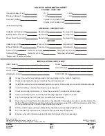
I - Set Points
Set Points
Sta tus
BACOid
Economizer En able
ON
29747
Power Ex haust En able
ON
29787
Non-Mod u lat ing Power Ex haust
ON
29503
These settings can be accessed within the RTU- SE UCB
menu. Please refer to the RTU's SE "
Quick Start
" guide
for menu navigation using the onboard LCD display,
joystick and enter/cancel buttons.
Please see the
following pages for instructions on how to navigate
the Smart Control (SE) menus and setting up the
control to operate with an ERV.
II - SE Procedures to Backup / Restore
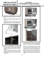
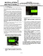
1.
Once the packaged unit is powered up the 120 second
startup delay begins. Once the delay expires there
may or may not be a "
Start Up
" delay displayed. To
cancel the second time delay press the "
Cancel
"
button for six seconds.
See Figure 1.
Startup
Figure 1
Update
Figure 2
Backup
Figure 3
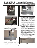
2.
Once the control is out of time delay mode, press the
Joystick down through the following menus:
Status>
Alarms> Summary> Commission> Controller>
Update, Push ENTER
(
See Figure 2
)
3.
Once the screen and cursor are on "
Update
".
Press
Enter
and scroll through the menus until the
screen and cursor displays "
Backup
". If an USB flash
drive is present or is inserted into the on board USB
port, pressing enter when "
Backup
" is displayed the
backup will begin sending factory defaults and other
settings to the USB flash drive.
See Figure 3.
4.
Once the backup is performed (Screen shows BCFG
100%) the 3.1 or greater version of the controls
firmware can be loaded. Please see the details on the
following pages on how to perform the firmware
updates.
III– SE Procedures to Update
Updating the program in the SE control by USB if
required.
WARNING!
In order for the ERV to properly operate with
the SE control version 3.1.0.0.0128 or greater must be
installed. Load the appropriate files to a clean USB Flash
Drive as indicated in the prior five steps.
(Files located on UPGNET>UST and Technical
Services Center>Tech Services Software Updates)
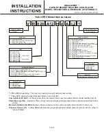
Summary of Contents for VR028A15H
Page 9: ...PAGE 9 ...
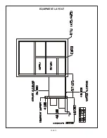
Page 12: ...PAGE 12 EQUIPMENT LAYOUT ...


