


PAGE 15
MAXA-MI$ER
Ô
UNITARY ENERGY RECOVERY VENTILATOR
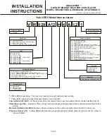
MODEL VR028A15M/H & VR028A25H (STATIONARY)
INSTALLATION
INSTRUCTIONS
5257527-UAI-A-0616 / R28A-18YSDW
8.
Press
ENTER
again.
Screen will read
FWU WAIT
then the program will load.
This could take up to 10 minutes or more. The screen
contents will change several times during the update so
be
patient…
Wait until base screen reappears. Re-programming is
complete for the firmware. Now that the new firmware is
loaded it is time to restore the backup data from earlier
s t e p . S c r o l l t o :
S t a t u s > A l a r m s > S u mm a r y>
Commission> Controller> Update> View Version>
Load Firmware> Backup> Restore
press
Enter
and the
screen will request the user indicate which restore file to
use. The backup files should be named after the units
serial number. Scroll to the appropriate units serial number
on the screen and press
Enter
. The restore should only
take 15-20 seconds. Once the restore is complete the SE
unit control will reboot.
Note: If updating a version "H"
board it may require two firmware updates to take
place. Please verify the active version of firmware after
updating.
If the unit does not reboot, restart cycle power to the unit
and wait again for re-boot start-up.
If loading more than one file, example upgrading CDR unit
from version 1, you should cycle power after loading the
first file and again after the last file is complete.
It is a good practice to conduct a "RE-LEARN" from within
the menu after the file(s) have been upgraded if the
function of the unit does not appear to be normal.
Status>
Alarms> Summary> Commission> Controller>
IV - SE Procedures to Setup Operation for ERV
In order for the SE unit controller, SE economizer control
a n d E R V t o o p e r a te p r o p e r l y t h e f o ll o w i n g
changes/settings will need to be performed within the SE
unit control.
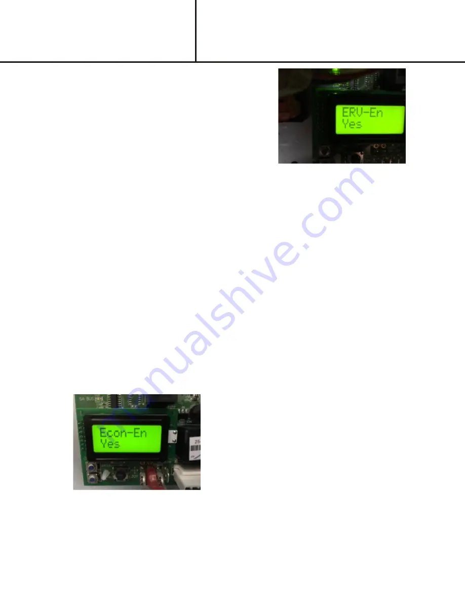
1.
Scroll through menus by pressing down on joystick:
Status> Alarms> Summary> Commission> Econ>
Economizer Enable- Make sure this is set to "Yes"
ERV-En
Figure 11
Econ-En
Figure 10
2.
Scroll through menus by pressing down on joystick:
Status> Alarms> Summary> Commission>
PowerEx> ERV Enable- Make sure this is set to
"Yes"
3.
The economizer minimum setting must be set at 50%
or greater.
Status> Alarms> Summary> Commission>
PowerEx> ERV Enable- Make sure this is set to
"Yes"
4.
Once the ERV is set to "
Enable
" the ERV will operate
any time the unit is in the occupied mode. The ERV, if
equipped with pivoting wheel, will rotate the wheel out
of the air stream anytime the packaged units
economizer enters the free cooling mode. In order to
test for proper operation the unit must see a call for
cooling (24 vac on the Y1 terminal) and an outdoor
temperature of 55
o
F or less. If the outdoor ambient
temperature is above 55
o
F the unit may not enter free
cooling. If the ambient temperature is above 55
o
F the
packaged unit can be forced into free cooling mode by
doing the following:
5.
Scroll through menus by pressing down on joystick:
Status> Alarms> Summary> Commission>
Controller> Update> Details,
under details press
Enter
then scroll to the Service
menu heading, press
Enter
then scroll to
Inputs>
NetworkInputs
, scroll to
NetOAT
and change it to a
setting well below the 55
o
F default by toggling the
joystick left or right to increase/decrease the value,
then pressing
Enter
to store the new value. If the
setting is now 30
o
F for example the unit should go into
free cooling mode within a few minutes of the
change. Note: Once the NetOAT is forced to a
temperature below 55
o
F
it will remain at the forced
value for 15 minutes and revert back to default
settings.
For additional details on navigating, changing and
operating the SE unit control board please refer to the
SE (Smart Equipment) Controls Quick Start Guide
(Document # 1136326-USG-C-0216) that is shipped
with the packaged unit.
Summary of Contents for VR028A15H
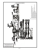
Page 9: ...PAGE 9 ...
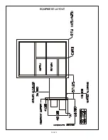
Page 12: ...PAGE 12 EQUIPMENT LAYOUT ...


