


PAGE 5
During both the summer and winter, the UERV transfers
moisture entirely in the vapor phase. This eliminates wet
surfaces that retain dust and promote fungal growth as well
as the need for a condensate pan and drain to carry water.
Because it is constantly rotating when in the air stream, the
UERV is always being cleared by air, first in one direction
then the other. Because it is always dry, dust or other
particles impinging on the surface during one half cycle,
are readily removed during the next half cycle.
Additional Information for Options are provided in
Options Manual.
Re cov ery Mode
On a thermostat call for blower operation in heating,
cooling or continuous blower, the ERW will rotate between
fresh air and exhaust air streams. Both the fresh air and
exhaust air blowers will also be operating to overcome the
air resistance of the UERV.
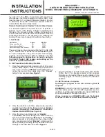
Free Cool ing Mode (op tional)
The Start, Stop, Jog kit is an optional control board with
temperature and/or enthalpy sensor(s) that stops the
enthalpy wheel from spinning (and transferring heat) when
temperature conditions are conducive for free cooling.
The board will spin the wheel intermittently in 10 min off 1
min on intervals to keep dust from building up on the
surface.
All units shipped with the Start, Stop, Jog option installed
have the temperature and enthalpy sensors installed, and
the jumper (J9) set to T(emp). A qualified tech can adjust
the setting to E(nthalpy) only or Temp and Enthalpy by
adjusting the jumper (J9).
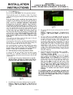
The factory set points to allow for free cooling during
ventilation are 40
o
F-70
o
F, but they can be field adjusted to
narrow the band by adjusting two potentiometers while
measuring VDC between the Com & High or Com & Low
terminals (0 VDC = 40 degrees, low set point, 5 VDC = 70
degrees, high set point).
IX - Sys tem Check
1.
Disconnect main power.
2.
Turn thermostat to "Cont" for blower operation.
3.
Restore power to unit. Observe UERV wheel rotation
and both fresh air and exhaust air blowers will
operating.
Note: If Low ambient kit is used the jumper between
TB37-5 & TB37-6 should be removed. Also if
system check out is being conducted at low
ambient temperatures, technician should be
aware that this kit can cause system not to
operate.
4.
Verify that the UERV (3) three phase blower motors
are phased sequentially ensuring correct rotation and
operation.
a) Disconnect power.
b) Reverse any two field power leads to the UERV.
c)
Reapply power.
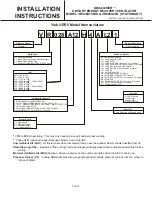
MAXA-MI$ER
Ô
UNITARY ENERGY RECOVERY VENTILATOR
MODEL VR028A15M/H & VR028A25H (STATIONARY)
INSTALLATION
INSTRUCTIONS
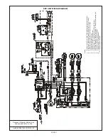
5257527-UAI-A-0616 / R28A-18YSDW
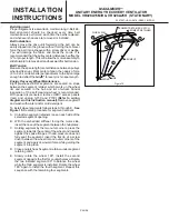
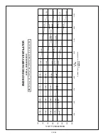
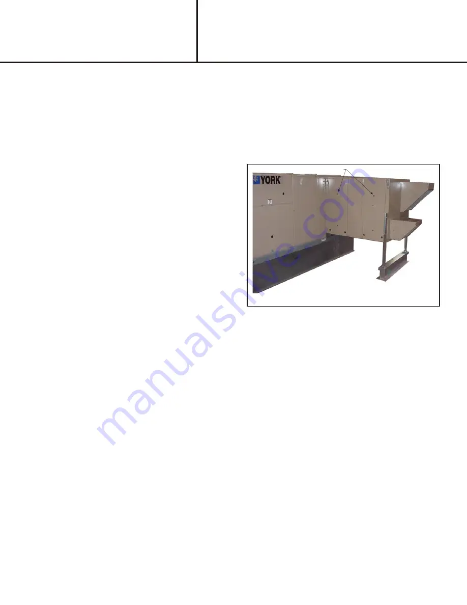
DELTA PRESSURE
Figure 14
A - Return Damper Set tings
Manually adjust position of dampers. This is accomplished
by loosing and tightening set screw on positioning rod.
B - Blower Speed Ad just ment
Blower speed selection is accomplished by changing the
sheave setting on both fresh air and exhaust air blowers.
Both blowers are factory set at "closed" for maximum
airflow. To determine air flow setting, external static
pressure readings will need to be read across the UERV.
See Figure 14
for location to take pressure readings.
C - Air Bal anc ing Ad just ment
1.
Remove plastic plugs in door panels (4 total).
2.
With a manometer measure the pressure drop [Inches
Of water column] across the wheel on the supply
airflow side of the unit (Top). The unit’s CFM is
determined by referring to
Table #1
. If the Cfm value is
not per design adjust the motor sheave until the
desired CFM is reached.
3.
To adjust the exhaust airflow check the pressure on
the exhaust side of the unit (Bottom), then remove the
door panel to access the return air dampers installed
inside the RTUs return air section. Adjustment of the
damper is made by loosening the wingnut, adjusting
the damper blades and then tightening the wingnut
before closing the panel and measuring again.
4.
Once desired the CFM is reached replace the plastic
plugs in the access holes in the doors.
X - Main te nance
Motor Maintenance
All motors use prelubricated sealed bearings; no further
lubrication is necessary.
Mechanical Inspection
Make visual inspection of dampers, linkage assemblies
and UERV rotating bearings during routine maintenance.
Filters should be checked periodically and cleaned when
necessary. Filter is located in fresh air hoods.
DO NOT
replace permanent filters with throwaway type filters.
Summary of Contents for VR028A15H
Page 9: ...PAGE 9 ...
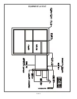
Page 12: ...PAGE 12 EQUIPMENT LAYOUT ...


