


PAGE 8
E
N
E
R
G
Y
R
E
C
O
V
E
R
Y
V
E
N
T
IL
A
T
O
R
S
C
F
M
v
s
.
P
R
E
S
S
U
R
E
D
R
O
P
0
.5
3
0
.5
7
0
.6
0
0
.6
4
0
.7
1
0
.7
8
0
.8
5
0
.9
3
1
.0
0
1
.3
0
1
.3
1
1
.3
1
1
.3
0
1
.2
8
1
.2
6
1
.2
0
1
.1
3
1
.0
4
1
.0
9
1
.0
9
1
.0
9
1
.0
8
1
.0
5
0
.9
9
0
.9
0
0
.8
2
0
.7
5
0
.8
9
0
.8
8
0
.8
7
0
.8
5
0
.8
1
0
.7
5
0
.6
6
0
.5
9
0
.5
0
.6
9
0
.6
8
0
.6
5
0
.6
2
0
.5
7
0
.5
0
.4
2
0
.3
5
0
.2
5
0
.0
0
0
.2
0
0
.4
0
0
.6
0
0
.8
0
1
.0
0
1
.2
0
1
.4
0
1
5
0
0
1
6
0
0
1
7
0
0
1
8
0
0
2
0
0
0
2
2
0
0
2
4
0
0
2
6
0
0
2
8
0
0
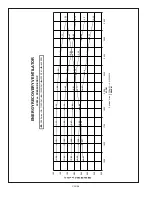
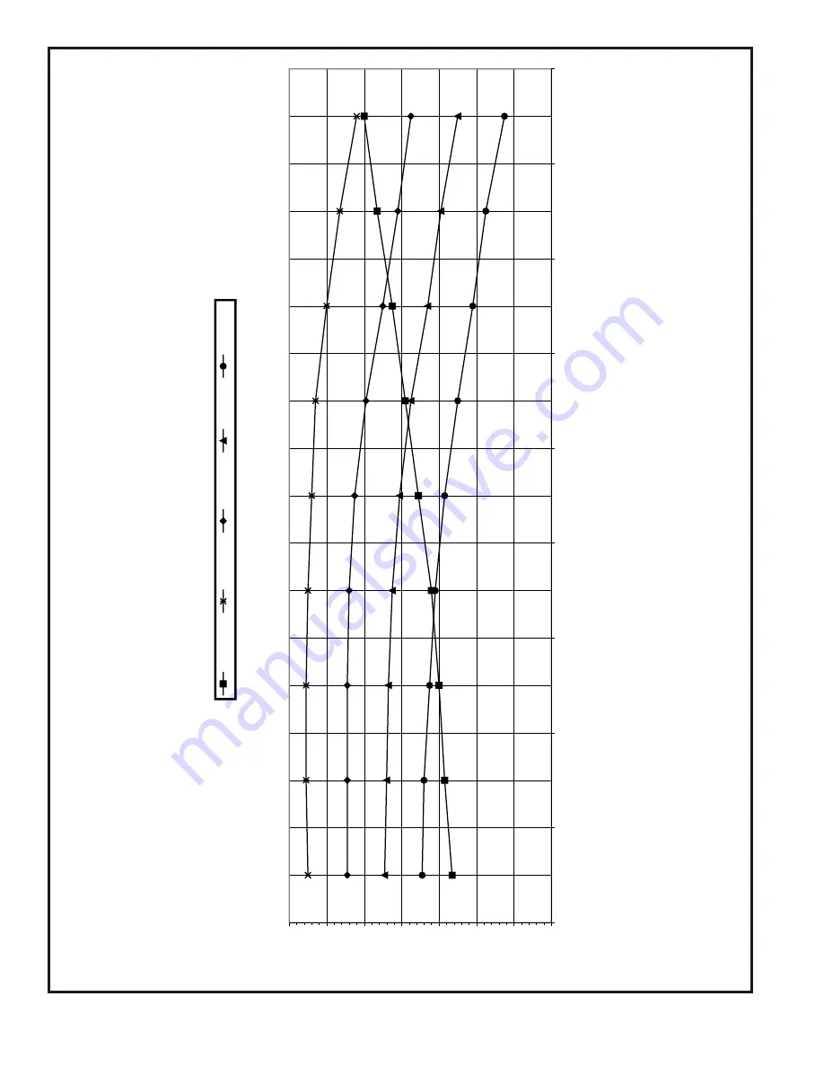
S
C
F
M
E
q
u
a
ti
o
n
o
f
lin
e
:
S
C
F
M
=
(P
D
+
0
.0
1
)/
0
.0
0
0
3
6
T
A
B
L
E
#
1
PR
ES
SU
RE
DR
OP
(in
.o
fW
.C
.)
R
2
8
S
e
ri
e
s
1
1
0
0
R
P
M
1
0
0
0
R
P
M
9
0
0
R
P
M
8
0
0
R
P
M
Summary of Contents for VR028A15H
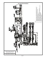
Page 9: ...PAGE 9 ...
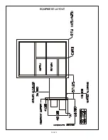
Page 12: ...PAGE 12 EQUIPMENT LAYOUT ...


