7.3
Refrigerant Charge
YCAA-H R22 units must only be charged on
the cooling circuit. Never introduce liquid
refrigerant in the low pressure side of circuit.
Extreme care must be taken to ensure that
circuit is correctly charged.
YCAA-B R407C units must be charged when
the refrigerant is in the liquid phase to ensure
correct refrigerant mix is maintained. A
service valve is provided for charging the unit
at low pressure.
An insufficient charge will lead to poor machine
performance. In extreme cases, the low pressure switch
will cut in and lock the circuit.
Excessive charge will raise the condensation pressure
(which in extreme cases will cause the high pressure
switch to cut in and lock the circuit) with a consequent
increase in power consumption.
Under no circumstances must the
compressor be used as a vacuum pump to
purge circuit.
The refrigerant circuit must be charged whenever it is
emptied for maintenance purposes (leak repair,
compressor replacement, etc.). Charge quantities are
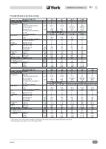
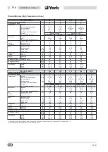
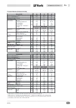
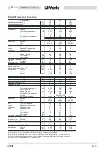
given in Section 9.
Before charging, the circuit must be vacuum-purged
and dried, reaching a minimum absolute pressure of
50 Pa.
7.4
Compressors
Compressors are supplied with the correct quantity of
lubricant required for operation. Under normal operating
conditions, lubricant will last the life of the unit. Fluid
top-up is not required as long as refrigerating circuit
operates correctly and no repair operations have been
carried out.
Compressor replacement (as a result of failure), should
be carried out by an Authorised York Service Centre.
7.5
Condenser Coils
Condenser coils feature copper tubes and aluminium
fins. Should refrigerant leakage take place as a result of
accidental impact or damage. The coils must only be
repaired or replaced by an Authorised York Service
Centre.
To ensure high condenser coil serviceability and heat
exchange, the condenser surfaces must be kept free of
impurities such as leaves, fibres, insects, dirt, etc.
Soiled condenser coils will increase power
consumption. In addition, the maximum pressure alarm
may cut in and lock out the unit.
Take care not to damage aluminium fins
during cleaning.
The condenser should be cleaned using compressed
air directed parallel to aluminium fins and in the opposite
direction to that of normal air circulation. A vacuum
cleaner may be used to clean the condenser coil from
outside. The coil may also be cleaned with soapy water
using a suitable spray nozzle.
7.6
Condenser Fans
Each condenser fan features a wing-profile impeller and
cylindrical nozzle. The fan motor bearings are lubricated
for life.
7.7
Filter Drier
Refrigerating circuits are provided with filter/driers.
The filter/driers are non-inspectable strainer type.
Filter/drier clogging will be indicated by bubbles in the
sight glass, or by a difference in temperature upstream
and downstream of filter/drier.
If bubbles persist after the changing cartridge, the
machine has lost part of its refrigerant charge through
one or more leaks which must be identified and
repaired.
7.8
Sight Glass
The sight glass is used to observe refrigerant flow and
moisture content. Bubbles in flow indicate that filter/drier
is clogged, or that refrigerant charge is low.
A colour indicator is located inside the sight glass.
Compare the colour of the indicator with the scale on the
sight glass lock ring to determine the moisture content of
refrigerant. If moisture content is too high, proceed as
follows:
n
Discharge the circuit without releasing refrigerant
to the atmosphere. Vacuum-purge the circuit and
replenish the charge.
(09/03)
7
-
2
035B09012-100 Rev. 4
Summary of Contents for YCAA B 120
Page 2: ......
Page 16: ...This Page Left Intentionally Blank 09 03 2 6 035B09012 100 Rev 4 ...
Page 28: ...This Page Left Intentionally Blank 09 03 4 10 035B09012 100 Rev 4 ...
Page 36: ...Page Left Intentionally Blank 09 03 6 6 035B09012 100 Rev 4 ...
Page 40: ...Page Left Intentionally Blank 09 03 7 4 035B09012 100 Rev 4 ...
Page 68: ...Notes 09 03 11 2 035B09012 100 Rev 4 ...
Page 69: ...Notes 09 03 035B09012 100 Rev 4 11 3 ...

