background image

035-15806-004 Rev. A (1000)

Unitary Products Group

7

LOW VOLTAGE

Control wiring may vary, depending upon the type of thermo-
stat, furnace or air handler being connected.

Low voltage wiring diagrams can be found with the furnace or
air conditioning blower package installation instructions.

Pig-tail connector wires are provided from the low voltage
pull-in coil on the contractor to a section of the control box. A
“fingered" bushing is provided in the low voltage knockout
hole. If 1/2" conduit is used for the low voltage wiring, the
bushing is to be removed.

1.

Route the low voltage cable through the fingered bush-
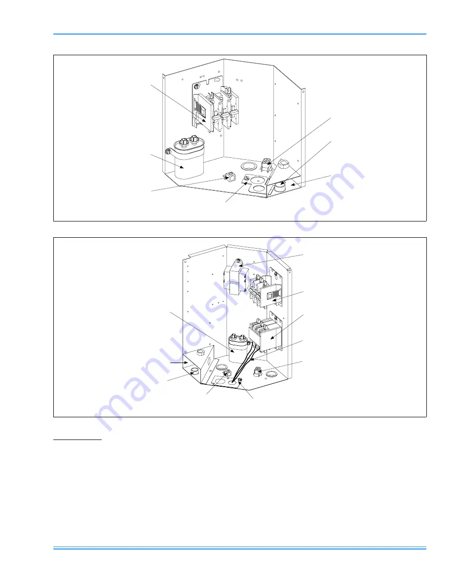
ing in the low voltage junction box. See Figure 3 or 4.

2.

Using wire nuts, connect the low voltage wiring as shown 
in Figure 5, 6 or 7.

3.

A minimum of 18 AWG wire gauge for total lengths not 
exceeding 130 feet must be used in connecting the low 
voltage control wiring between the outdoor unit, furnace 
and thermostat. For longer low voltage control wiring 
lengths, consult the N.E.C.

Connect thermostat and control package wiring as shown in
Figure 5-7 and per the instructions packed with those pieces. 

 FIGURE 3 : 

OUTDOOR UNIT CONTROL BOX (036, 048 & 060 MODELS)

CONTACTOR

FAN CAPACITOR

GROUND LUG

REVERSIBLE HIGH VOLTAGE
CONDUIT PLATE

LOW VOLTAGE
BOX

“FINGERED”
BUSHING

FAN MOTOR
PLUG

 FIGURE 4 : 

OUTDOOR UNIT CONTROL BOX (076 & 090 MODELS)

CONTACTOR 1

FAN CAPACITOR

GROUND LUG

ADJUSTABLE HIGH VOLTAGE
CONDUIT PLATE

LOW VOLTAGE
BOX

“FINGERED”
BUSHING

FAN MOTOR
PLUG

POWER WIRING
CONNECTIONS

CONTACTOR 2

(090 ONLY)

TRANSFORMER

Summary of Contents for 3 PH

Page 1: ...NIT 4 INDOOR UNITS 4 REFRIGERANT LINE 4 INSULATION OF VAPOR LINE 4 RE ASSEMBLING BRAZING AND CLEANING OF JOINT CONNECTIONS 5 REFRIGERANT LINE SUPPORT 5 CHARGING AND LEAK TESTING 5 TOTAL LINE LENGTH 5...

Page 2: ...any additional external static pressure The maximum and minimum conditions for operation must be observed to assure a system that will give maximum perfor mance with minimum service Check Electrical...

Page 3: ...ences standing off from the coil can reduce capacity loss due to wind chill effect Provide ample clearance from shrubs to allow adequate air to pass across the outdoor coil without leaves or branches...

Page 4: ...istance and fewest number of bends Determine the path that the refrigerant lines will follow Starting at either the indoor coil or the outdoor unit refrigerant line connections carefully measure cut d...

Page 5: ...tamination Contaminated refrigerant must be recovered and returned to the local refrigeration supply house for proper disposition TOTAL LINE LENGTH Units should be installed only with approved system...

Page 6: ...t include a disconnect switch located within sight of the outdoor unit 2 Use the correct size fuse or circuit breaker as listed on the unit rating plate and data sheet See Tabular Data Sheet for minim...

Page 7: ...3 or 4 2 Using wire nuts connect the low voltage wiring as shown in Figure 5 6 or 7 3 A minimum of 18 AWG wire gauge for total lengths not exceeding 130 feet must be used in connecting the low voltage...

Page 8: ...TACTOR 1 TERMINALS GND LUG R B Y O W R Y G AIR HANDLER TERMINAL BLOCK 4TB TYPICAL THERMOSTAT ALL OUTDOOR WIRING MUST BE WEATHERPROOF USE COPPER CONDUCTORS ONLY X 53 G 60 66 JUNCTION BOX RED BRN YEL OR...

Page 9: ...see that nothing was over looked Have all braze joints on refrigerant lines been leaked checked Have base valves been opened Have all refrigerant lines been secured and iso lated properly Is the indo...

Page 10: ...035 15806 004 Rev A 1000 10 Unitary Products Group NOTES...

Page 11: ...035 15806 004 Rev A 1000 Unitary Products Group 11...

Page 12: ...without notice Printed in U S A 035 15806 004 Rev A 1000 Copyright by York International Corp 2000 All rights reserved Supersedes 035 15806 403 REV A 550 46 N2Y 499 Unitary 5005 Norman Product York OK...

Reviews: