After determining the best orientation, lay the unit on top of the
shipping carton to protect the finish. The appropriate electrical
knock-outs for power wiring, control wiring and gas piping
should be removed at this time.
For horizontal application, return air may enter through the end
only. Return air may not be connected into the rear panel
of the unit.
Horizontal Filters
All filters and mounting provision must be field supplied. Fil-
ters(s) may be located in the duct system external to the
furnace or in a return filter grille(s).
ATTIC INSTALLATION
This appliance is design certified for line contact for furnaces
installed horizontally. The intersection of the furnace top and
sides form a line. This line may be in contact with combustible
material. However, refer to "Venting" and "Clearances" in this
manual for additional information.
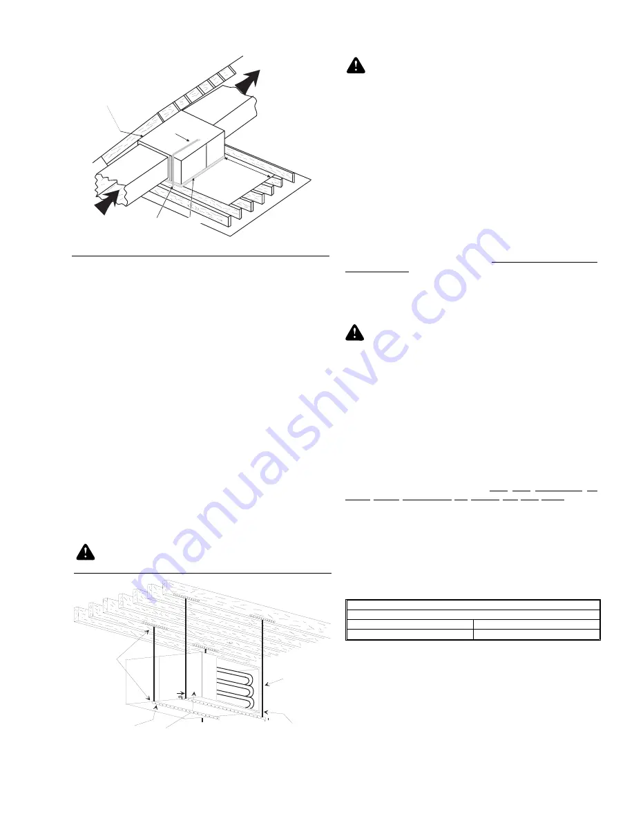
Secure a platform constructed of plywood or other building
material to the floor joists. Refer to Figure 6 for details.
NOTE: The unit must be elevated to allow clearance
for the condensate trap and drain pipe.
CAUTION: If this furnace is installed over a finished
space a condensate safety pan must be installed.
WARNING: When a furnace is installed in an attic or
other insulated space, keep all insulating materials at
least 12" away from furnace and burner combustion
air openings.
NOTE: See crawl space installation for suspending
the furnace in attic installations.
CRAWL SPACE INSTALLATION
The furnace can be hung from floor joists or installed on
suitable blocks or pad. Blocks or pad installations shall provide
adequate height to ensure the unit will not be subject to water
damage.
When suspending the furnace from rafters for floor joists using
rod, pipe or straps, refer to Physical Data (Page 4 or 5) for
furnace weights to determine suitable means of suspension.
Angle supports should be placed at the supply air end and near
the blower deck. Refer to Figure 7. Do not support at return
air end of unit.
Units may also be suspended by using straps or other material
at the same location. All four suspension points must be level
to ensure quiet furnace operation.
CAUTION: In any application where temperatures
below freezing are possible, refer to Page 6, "Below
Freezing Locations."
GAS PIPING
The gas supply must be installed in accordance with the current
National Fuel Gas Code, ANSI Z223.1 (in the U.S.) or
CAN/CGA-B149.1 or .2 (in Canada) installation codes and all
applicable local and utility requirements. All pipe and fitting
material, pipe size and installation procedures must comply
with the appropriate code. Some utilities may require larger
pipe sizes than shown in the code. Gas piping may be con-
nected from either side of the furnace. Each side of the unit has
two gas pipe entry knockouts.
For downflow/horizontal models, plan your combustion air
piping before determining the correct gas pipe entry. Use 90
degree service elbow(s), or short nipples and conventional 90
degree elbow(s) to enter through the cabinet access holes.
NOTE: An accessible manual shutoff valve must be installed
upstream of the furnace gas controls and within 6 feet of
the furnace.
The installation of a ground joint union and drop leg are
required. Refer to Figure 8. Maximum and minimum supply gas
pressures are shown below:
NOTE: A 1/8" NPT plug is included in the inlet side of the gas
valve for measuring incoming gas pressure.
The furnace must be isolated from the gas supply piping
system by closing its individual external manual shutoff valve
during any pressure testing of the gas supply piping system at
pressures equal to or less than 1/2 psig (3.48 kPa).
The furnace and its individual shutoff valve must be discon-
nected from the gas supply piping system during any pressure
testing of that system at test pressures in excess of 1/2 psig
(3.48 kPa).
INLET GAS PRESSURE
Natural Gas
Minimum
4.5 In. W.C
Maximum
13.8 In. W.C.
G A S P I P I N G
S E D I M E N T T R A P
3 0 " M I N
W O R K A R E A
R E T U R N A I R
S U P P L Y A I R
L I N E C O N T A C T O N L Y P E R M I S S I B L E
B E T W E E N L I N E S F O R M E D B Y T H E
I N T E R S E C T I O N O F F U R N A C E T O P
A N D T W O S I D E S A N D B U I L D I N G
J O I S T S , S T U D S O R F R A M I N G
S A F E T Y P A N
FIGURE 6 - TYPICAL ATTIC INSTALLATION
S U P P O R T
R O D
A N G L E I R O N
B R A C K E T
6 " M I N B E T W E E N
R O D & F U R N A C E
1 " M A X B E T W E E N
R O D & F U R N A C E
1 " M A X B E T W E E N
R O D & F U R N A C E
FIGURE 7 - TYPICAL FURNACE INSTALLATION
USING SUSPENSION MATERIALS
650.75-N4U
Unitary Products Group
9


