JOHNSON CONTROLS
20
FORM 102.20-OM2
ISSUE DATE: 6/01/2015
SECTION 2 - START-UP AND OPERATION
Airflow Control Dampers
Many combinations of damper sizes are available to
control the flow. Mixing the return and outside air in
the AHU's air inlet section may be supplied as follows:
•
100% outside air, 100% return air.
•
100% outside air, 0% return air.
•
0% outside air, 100% return air.
•
Economizer section - 100% outside air, 100% re-
turn air, 100% exhaust air or mixed air.
Check the dampers, actuators, controls and linkage
prior to applying power to the operators, to make sure
nothing will obstruct the operation of the dampers.
Do not overdrive the damper actuators
because this may damage the dampers.
Exception: Actuators with over drive
preset option.
Return air dampers may be closed for shipping. Loosen
the actuator or crank arm on the jackshaft, open the
dampers, and retighten the actuator or crank arm. The
field is responsible for adjustments.
Air Measuring Device Connections
Calculating Flow Rate
For a Piezoring:
CFM = k * ΔP
2
ΔP = The differential in static pressure across the fan
(inches w.g.)
k = See the table below
This assumes a standard air density of .075 lbs / cubic
foot at sea level.
For a Cometer:
CFM = k * ΔP
n
ΔP = The differential in static pressure across the fan
(inches w.g.)
k = See the table below
n = See the table below
This assumes a standard air density of .075 lbs / cubic
foot at sea level.
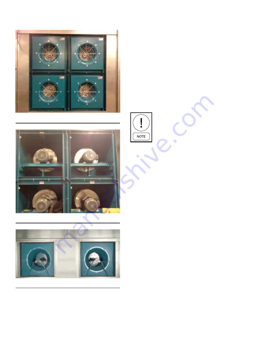
Examples of Fan Arrays
FIGURE 8 -
FRONT OF A 2X2 FAN ARRAY
LD17226
FIGURE 9 -
BACK OF A 2X2 FAN ARRAY
LD17227
FIGURE 10 -
FRONT OF A 1X2 FAN ARRAY
LD17230


